- All
- Product Name
- Product Keyword
- Product Model
- Product Summary
- Product Description
- Multi Field Search


SP1-C series SPD is suitable for TT, IT, TN-S, TN-C-S power supply system with AC 50/60Hz, 230/400V and below. Its design based on IEC6143-1, GB18802.1 and GB50057 standard requirements.
| Quantity: | |
|---|---|


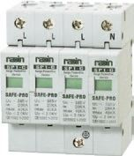
SP1-C (Class II Protection)
Application
SP1-C series Type 2 Surge Protective Devices are suitable for TT, IT, TN-S, TN-C-S power supply system with AC 50/60Hz, 230/400V and below. Its design based on IEC6143-1, GB18802.1 and GB50057 standard requirements. It is mainly used for protect the low voltage electrical device and the surge current caused by air discharge (such as lightning) or operating over voltage. Used as one kind of voltage limiting device, it equipped with heavy duty zinc oxide varistor.
SP1-C type Type 2 Surge Protective Devices should be installed as near as possible to the upstream line side of the protected equipment (immediately connect to the downstream of incoming line), as earthing device to connecting external conductor (L) or neutral line and user equipment. It should be installed at transition area of LPZOA/OB and LPZ1 zone or LPZ1 and LPZ2 zone, normally installed at the incoming of low voltage main distribution board.
Main Technical Parameters
Classification | SP1-C (Class II Protection) | |||||
Poles | 1P, 2P, 1P+N, 3P, 3P+N, 4P | |||||
Rated Operating Voltage Un (V) | 230/400 | |||||
Nominal Discharge Current In (8/20µs) KA | 20 | |||||
Max. Discharge Current Imax (8/20µs) KA | 40 | |||||
Max. Continuous Operating Voltage Uc (V) | 275 | 320 | 385 | 420 | 440 | |
U1mA Varistor Voltage (V) | 430 | 510 | 620 | 680 | 710 | |
Protection Level Up (KV) | <1.5 | <1.6 | <1.8 | <2.0 | <2.2 | |
Response time (ns) | <25 | |||||
Leakage Current 75% Uc 1mA | <20μA | |||||
Test classification | Class II | |||||
Protection Degree | IP20 | |||||
Max. Ambient Temperature | -40℃ ~+80℃ | |||||
Insulation enclosure material | PBT/PA66 | |||||
Flame Resistance Grade confirm to UL94 | VO | |||||
Installation Mode | 35mm standard rail | |||||
Enclosure Color | White/Gray | |||||
Suggested Fuse or circuit breaker (A) | 40~63 | |||||
Conductor cross section (mm2) | Phase line, Neutral line | 4-16 hard wire | ||||
Earthing Line | 4-16 dual color | |||||
Standard | GB18802.1 GB18802.21 IEC61643-1 IEC61643-21 UL1449 ed.2 | |||||
Technical Terms
● Surge Identification Technology Introduction:
Surge identification arrester comprised of surge switch, multi-group MOV and one series of thyristor (as below chart):

The surge switch is controlled by a surge identification circuit, which is closed when a high-frequency surge arrives at the station, and the MOV is connected to the circuit for protection. Under the general cycle of overvoltage, MOV is not connected to the circuit. So, this kind of device has high sustained overvoltage value. By the MOV in ordinary without access circuit, extremely slow aging, so life is very long (five years warranty).

By ding MOV loop series surge switch, although this switch action quickly, but in any case will lengthen the loop response time, increase the residual pressure of components, reducing the protection performance. In order to solve this problem. "in order to protect" technology is adopted in circuit.
Previously we mentioned that the zener diode has fast response speed, but lower energy absorbs capability. If add the zener diode in the circuit ( as above chart), when lightning surge arrive, zener diode first triggered, later on, the surge switch closed, MOV connect to the circuit(zener diode disconnected, zener diode only working at the first tens of nanosecond), discharge most of lightning current. The result of such arrangement, make the element have zener diode's characteristic of fast action and short response time. Moreover, as the zener diode action time only have tens of nanosecond, therefore, use one series diode is enough, will not bring manufacturing cost and reliability problem.
Due to the combined application of "Surge switch" and "sequence Protection Technology", make the surge identification power supply protector have the following characteristics:
○ Maximum allowed continuous over voltage 480V, comply with the requirements of international safety standard 1449.
○ Response time<5ns
○ Residual voltage: 730V(3KA, 8/20µs)
○ Under normal status, MOV not connect into the circuit, therefore aging very slow, long working life.
Selection of Type 2 Surge Protective Devices
With the impact of international information flow, the rapid development of microelectronic science and technology, communication, computer and automatic control technology, make the building start to go for high quality, high functional area, formed a new building style—intelligent building. As inside the intelligent building there are lot of information system,
《Building lightning protection design norm》GB50057-94(2002 vision)(hereafter brief as 《lightning protection norm》) put forward the relative requirement to install the surge protective device, to ensure the information system safely and stable running.
SPD essentially is a equipotential connection material, and its model selection is according to the different lightning protection area, different lightning electromagnetic pulse critical and different equipotential connection position, decide which kind of SPD used in the area, to achieve the equipotential connection with the common earth electrode. Our statement will based on SPD's maximum discharge current Imax, continuous operating voltage Uc, protection voltage Up, alarm mode etc.
As per《Lightning Protection Norm》item 6.4.4 stipulation "SPD must can withstand the expected lightning current flow and should confirm to the additional two requirements: the maximum clamp voltage during surge across, capable to extinguish the power frequency follow-on current after lightning current across." That is the value of SPD's max. clamp voltage add its induction voltage of two ends should be same with the system's basic insulation level and the equipment allowed max. surge voltage.
1. Maximum Discharge Current
As per 《 Lighting Protection Norm 》 item 6.4.6, the SPD which installed at the junction of LPZOA, LPZOB and LPZ1 area, the maximum discharge current calculate as followings:
As per 《 Lighting Protection Norm 》 stipulation of " 50% of lightning current flows to the building's lightning protective device, and the other 50% flows to various kind of building's external conductor, power cables, and communication cables etc. ", the first time lightning current refers to below chart:
Lightning current data | Class I lightning protective building | Class II lightning protective building | Class III lightning protective building |
I amplitude (KA) | 200 | 150 | 100 |
T1 wave head time | 10 | 10 | 10 |
T2 hemiwave time | 350 | 350 | 350 |
Lightning wave decomposed after it flows to the power cable, communication cable, metal tube etc. The lightning current shunt value of L.V distribution cable of main power distribution room calculate as chart 2, when line is shielded, the lightning current drop to 30% of its original value, as per 《 Communication Station's Lightning Protection Project Design
Norm 》 YD/T5098 stipulation, the electric charge qty of 10/350s waveform pulse is around 20 times of 8/20s simulating
lightning waveform's electric charge qty, detailed calculation as below chart (Power supply cable shunt value):
Lightning current data | Class I lightning protection building | Class II lightning protection building | Class III lightning protection building |
I amplitude (kA) | 200 | 150 | 100 |
Power supply cable total shunt value (kA) | 33.33 | 25 | 16.67 |
Each cable shunt value (kA) | 11.11 | 8.33 | 5.56 |
Tube shielded shunt value (kA) | 3.33 | 2.49 | 1.67 |
8/20s waveform conversion value (kA) | 66.6 | 49.8 | 33.4 |
Max. Discharge current of SPD (kA) | 100 | 65 | 40 |
Class I protection (suggested) | 100 | 65 | 40 |
Class II protection (Suggested) | 40 | 40 | 40 |
As per 《Lightning Protection Norm》Item 6.4.8 and item 6.4.9, the SPD installed at LPZ1 area and LPZ2 area (machine room distribution box), its nominal discharge current (Rated discharge current) should more than 5KA, select the maximum discharge current 40KA, nominal discharge current 10KA SPD as for Class II protection device.
2. Protection Voltage
Although it's important to select a suitable residual voltage of SPD, when the SPD for power supply system is installed in L.V power grid system, we should take more consideration of the system's residual voltage, that means when considering the SPD's residual voltage, at same time we should also considering the SPD installation affect to the system's residual voltage. For example the SPD installation as per picture (1), as at the lightning wave system, the current maximum average gradient value is not at the first time strike, it is at its following lightning strike, if according to
《 Communication Station's Lightning protection Project Design Norm 》 YD/T5098 stipulation, the wiring length should less than 0.5meter between the terminals of modularized device and phase line and null line, the requirement for earthing cable length less than 1 meter, so choose a suitable position in the low voltage distribution panel, it is possible to make the wiring length less than 1.0 meter, therefore its maximum average gradient, system residual voltage, SPD's protection voltage calculation as below chart (SPD's protection voltage selection):
Follow-on lightning current data | Class I lightning protection building | Class II lightning protection building | Class III lightning protection building |
I amplitude (KA) | 50 | 37.5 | 25 |
Wave head time(s) | 0.25 | 0.25 | 0.25 |
Max. Gradient di/dt (KA/s) | 3.32 | 2.5 | 1.68t |
Tube shielded shunt value (KA) | 0.83 | 0.625 | 0.42 |
1.0-1.5 m connection wire voltage drop L x di/dt (V) | 3320-4980 | 2500-3750 | 1680-2520 |
Power equipment insulation withstand voltage (V) | 6000 | 6000 | 6000 |
Class I SPD's max. protection voltage | 2680-1020 (17kA) | 3500-2250 (12.5kA) | 4320-3480 (8.4kA) |
From above chart, the Class I SPD's protection voltage Up for 4000V is not allowed; select protection voltage around 2000V is suitable.
Power distribute to each machine room distribution box, important power equipment, floor distribution box, have already been go through several time delay of cables, decoupling effect, its wave head time will be more than 10μs, the lightning current flow energy also have been after several times shunting reduction, energy will less than 5000A, therefore, the current max. average gradient=5KA÷2x30%÷10s=0.075KA/s. When SPD installation as per above picture(1): A, B max. surge voltage=UL1+Ur+UL2=0.1KV+Ur, (suppose L1+L2=1.5m), because machine room like Servers, computers, switching matrix etc. all belong to special protected equipment, its rated withstand impulse voltage is 1500V, at this point, the selected SPD's protection voltage should less than 1400V, therefore, Class II SPD's protection voltage (below 3-5KA) select less than 1200V is suitable.
3. Max. continuous operating voltage Uc
As per 《 Lightning Protection Norm 》 item 6.4.5, at TN power supply system, its Uc max. more than 1.15x220V=253V, meanwhile as per item 6.4.6 stipulation "At those location which the power supply voltage variation exceed 10% and harmonic wave make the voltage amplitude increase, according to the actual situation should increase the SPD's continuous withstand voltage", some of the distribution box manufacturer only select 275V, but we think in TN power supply system select 275V is not correct, the reasons as follows:
a) As we know GB50057 is formulated as per IEC standard, but IEC standard is mainly as per to western developed countries standard, its lightning protection also as per to developed countries high quality power grid, but our country power grid quality still have big difference with developed countries, especially for the failure voltage, voltage variation, voltage fluctuation, voltage distortion, harmonic interference, three phase unbalanced factor etc.. have big difference, at some area it is normal that the power supply voltage variation exceed ±15%;
b) As per GA173 《 Computer Information System 》 standard: the SPD's nominal break-over voltage should 2.2 times more than the system operation voltage, means at 220V operation system it should more than 484V; As we know that for voltage limiting type SPD, the main component is metal oxide varistor (MOV), as per MOV classification standard, from the relationship of continuous withstand voltage with MOV voltage (Nominal break-over voltage), we can find out that the MOV voltage is not a fixed value, it is a range, compare to 484V, we can know the continuous withstand voltage should more than 350V. Continuous withstand voltage and MOV voltage(Nominal break-over voltage) relationship as below chart:
Continuous withstand voltage (UC) | MOV voltage (V) | MOV voltage range (V) |
275 | 430 | 387-473 |
300 | 470 | 423-517 |
320 | 510 | 459-561 |
350 | 560 | 504-616 |
385 | 620 | 558-682 |
420 | 680 | 612-748 |
440 | 715 | 644-786 |
460 | 750 | 675-825 |
Continuous withstand voltage and residual voltage is a pair of contradictions, the more continuous withstand voltage, the more longer SPD working life, the more higher of residual voltage also; the lower continuous withstand voltage, the shorter SPD working life, and also the lower residual voltage; But under 5-10KA lightning current impulse, the comparison between SPD's continuous withstand voltage 350V and 440V, its residual voltage less than 100V, it will not increase the system residual voltage, therefore, we think to select higher continuous withstand voltage (like 440V) protector, to increase the protector working life is reasonable.
4. Leakage Current
As per GA173 《 Computer Information System Lightning Protective Device 》 item 6.1.1, the leakage current of parallel connection type SPD should less than 20µA, the more leakage current Io, the more possibility of SPD heating due to energy gathering, and the leakage current is increasing along with the MOV's temperature rising, therefore, the MOV will under vicious cycle status, this is also explained the leakage current increased along with the time variation ratio (increasing ratio) increase, the SPD energy gathering will more fast, thus the performance more worse, reduce the SPD working life, normally the leakage current of SPD less than 10µA is suitable.
5. Alarm Mode
Currently the alarm mode have three types, the first type is remote signaling alarm, suitable for unattended operation location; The another type is visible alarm, through mechanical design to achieve the alarm function, such alarm mode should make inspection after lightning strike or routine inspection, suitable for all locations, and it is now mostly used alarm mode; The third type is sound and light alarm, such alarm mode should add an alarm module, now lot of experts suggest to use cautiously. Because during lightning impulse, the sound and light alarm module may first attacked and lost its alarm function, and if the product also attacked and damaged, people will not aware it if rely on the sound and light alarm, then when second lightning comes, the lightning will get the chance to damage the protected equipment.
6. Structure Style
The structure style of SPD is very important, there are mainly two styles: Integrated modular design and pluggable modular design. The pluggable design have gap discharge due to it have plug gap exist, especially at the place which air humidity is relative large, this situation is more worse, make the SPD working life reduced. Integrated modular design didn't have any gaps, meanwhile it adopt 35mm DIN rail installation, easy for replacement.
Hot Tags: type 2 surge protective devices, China, suppliers, manufacturers, factory, price, discount