
- All
- Product Name
- Product Keyword
- Product Model
- Product Summary
- Product Description
- Multi Field Search
Views: 0 Author: Site Editor Publish Time: 2026-09-08 Origin: Site


Incorrectly sizing a backup power isolation system introduces severe operational and safety risks. Installing an undersized unit leads to catastrophic equipment failure, melted contacts, and electrical fires during peak load transfers. Conversely, oversizing without a clear engineering strategy results in wasted capital and overly complex installations. Facility managers and property owners face a strict balancing act. You must align generator output capacity, main service panel limits, and actual load requirements. Failing to do so guarantees code violations and facility downtime during critical outages.
Solving this problem requires a structured, engineering-based framework. You cannot guess electrical demands or rely on generic rules of thumb. Evaluating load demands accurately ensures you match generator specifications to the facility's infrastructure. This guide provides the exact methodology required to select the correct manual transfer switch for safe, compliant power isolation.
Transfer switch sizing must align with either the generator’s maximum continuous output or the facility's total calculated load, depending on the power management strategy.
For portable generators, the baseline sizing rule is to match the manual transfer switch to the amperage of the generator's largest heavy-duty receptacle.
Selecting the right switch requires categorizing the application scale—from 16A miniature DIN-rail switches for critical circuits to 3150A changeover switches for heavy industrial plants.
National Electrical Code (NEC) compliance dictates specific enclosure ratings (NEMA) and pole configurations (solid vs. switched neutral) based on the installation environment and generator bonding.
A correctly sized switch handles peak load demands without thermal degradation. It matches the generator's output profile while complying strictly with local electrical codes. Proper sizing guarantees complete physical isolation from the utility grid. This prevents dangerous backfeeding that threatens utility workers repairing downed lines. Success depends on defining the exact scope of your backup power strategy before you purchase any hardware.
The scope of your backup system fundamentally dictates the required switch sizing. Backing up an entire main service panel requires a heavy-duty switch rated for the full utility service. If your building has a 200A or 400A main service, the transfer mechanism must match that rating to handle the potential total load. This approach offers convenience because you do not have to rewire individual circuits. However, it demands a massive standby generator and expensive switchgear to support the entire building's demand.
Contrast this with a critical load sub-panel strategy. This method isolates only essential circuits. You might select server racks, refrigeration units, well pumps, or emergency lighting. By moving these specific circuits to a dedicated sub-panel, you can utilize a smaller, highly efficient switch. A 30A to 60A rating is often sufficient for these setups. This allows you to pair the system with a smaller generator, optimizing both your installation footprint and fuel consumption during extended outages.
Calculating the minimum switch rating requires basic electrical math. You must convert the generator's running wattage to amperage. Use the standard formula: Watts divided by Volts equals Amps. For example, a 7,500-watt generator running at 240 volts produces 31.25 amps. In this scenario, a 30A switch is undersized for peak output. A 40A or 50A switch becomes the correct choice to provide a safe operating margin.
Sizing solely based on the main service panel often leads to expensive errors. A 200A main panel does not automatically require a 200A transfer switch. If you only intend to back up 40 amps of critical sub-panel loads, installing a 200A switch wastes resources and complicates the wiring process. You must size the switch based on the actual load it will carry or the maximum output of the generator feeding it, whichever is the limiting factor.
Generator Running Watts | Voltage | Calculated Amperage | Recommended Minimum Switch Size |
|---|---|---|---|
5,000 W | 240V | 20.8 A | 30A |
7,500 W | 240V | 31.25 A | 40A or 50A |
12,000 W | 240V | 50.0 A | 60A |
20,000 W | 240V | 83.3 A | 100A |
For portable backup power, the industry-standard heuristic is straightforward. Match the switch rating to the largest outlet on the generator. Most heavy-duty portable generators feature a 30A (L14-30R) or 50A (14-50R) twist-lock receptacle. If your generator maxes out at a 30A outlet, your switch should be rated for 30A. This ensures the switch can handle the maximum current the generator can physically output through a single connection.
Integration requires matching every component in the chain. The Power Inlet Box (PIB), the connecting generator cord, and the transfer switch must share identical amperage ratings. A 50A switch fed by a 30A cord creates a system bottleneck and a severe overheating hazard. While this rule works perfectly for portable units, it falls apart when scaling up to standby commercial generators. Commercial units lack receptacles and require hardwired lug calculations based on maximum continuous output and specific wire gauges.
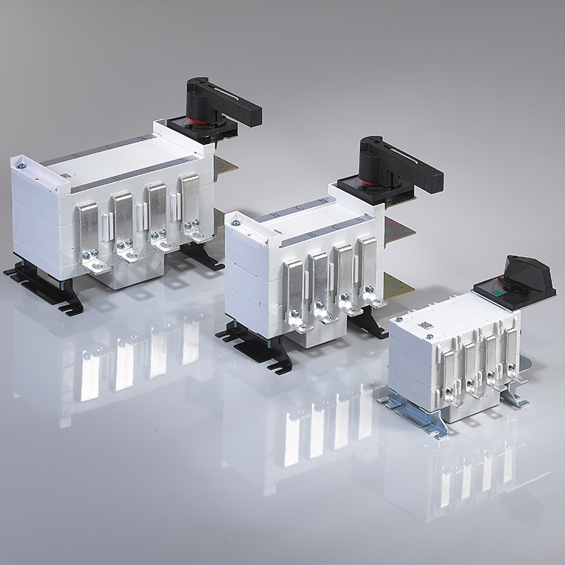
Market offerings break down into specific amperage tiers. Identifying your equipment category early prevents procurement mistakes. It also ensures physical compatibility with your existing electrical infrastructure and wire bending space requirements.
The 16A–63A miniature manual transfer switch category serves precise, low-draw applications. These units feature compact footprints designed for DIN-rail mounting inside existing enclosures. They are highly modular and easy to integrate into tight spaces where traditional bulky switchgear will not fit.
Use cases for this tier include critical load sub-panels in homes, telecommunications racks, and small residential solar integrations. When a grid goes down, these switches allow rapid toggling of specific circuits like well pumps, furnace blowers, or network servers. Their miniature design makes them ideal for localized power management without overhauling the main distribution board. Installers often use 10 AWG to 6 AWG wire for these connections, making them relatively easy to terminate.
Facilities with higher power demands require the 100A–630A manual transfer switch category. These units abandon plug-and-play connections in favor of hardwired, lug-based terminations. They utilize robust internal contacts designed to handle significant current without welding shut under load.
This tier supports whole-building backup for retail stores, mid-sized manufacturing facilities, and agricultural operations. A dairy farm relies on this size to keep milking equipment and cooling tanks operational during outages. The transition to this category requires careful attention to wire bending space within the enclosure. You must also use a calibrated torque wrench to tighten the lug connections to the manufacturer's exact inch-pound specifications. Loose connections at this amperage level will cause rapid heat buildup and eventual failure.
Massive infrastructure demands the 125A–3150A manual changeover switch category. These are heavy-duty devices engineered for extreme electrical environments. They feature massive copper busbars and heavy-duty mechanical linkages to physically move the large contacts safely.
Use cases include data centers, hospitals requiring non-life-safety redundant maintenance bypass, and heavy manufacturing plants. Evaluating this tier requires strict scrutiny of short-circuit withstand ratings (SCCR). The switch must survive massive fault currents until an upstream breaker trips. Arc-flash safety mechanisms and motorized operation capabilities are standard requirements at this scale. These features protect operators from arc blasts during load transfers. Wiring these units often involves parallel runs of 500 kcmil or larger cables, requiring specialized hydraulic crimping tools and extensive labor.
Selecting the right amperage requires looking through specific technical lenses. You must evaluate your facility's electrical demands based on how the power is actually consumed, not just the static numbers printed on a spec sheet.
The National Electrical Code (NEC) defines a continuous load as any circuit operating at maximum current for three hours or more. Commercial lighting systems, server racks, and EV chargers fall into this category. Standard breakers and switches are subject to an 80% derating rule. This means a 100A switch can only safely carry 80A of continuous load without overheating.
To calculate the necessary safety margin, you must multiply your total continuous load by 1.25. If your facility requires 160A of continuous power, you need a switch rated for at least 200A. Failing to apply this derating rule will cause the switch to overheat. This degrades the internal contacts, ruins the spring tension in the mechanism, and eventually causes a complete system failure.
HVAC systems, industrial pumps, and heavy machinery dramatically impact switch sizing. When a large motor starts, it draws a massive spike of current known as Locked Rotor Amps (LRA). This spike can be five to seven times higher than the motor's standard Running Load Amps (RLA).
If you transfer power while a heavy motor is attempting to start, the switch contacts must absorb that inrush demand. If the switch is undersized, the arcing caused by the LRA will pit and destroy the copper contacts. You must calculate the total RLA of your facility and add the LRA of the single largest motor to determine the absolute peak surge the switch will face. This ensures the contacts survive the initial transfer moment.
Equipment Type | Typical Running Load Amps (RLA) | Typical Locked Rotor Amps (LRA) | Impact on Switch Contacts |
|---|---|---|---|
Residential 3-Ton AC Compressor | 15 A | 75 A | Moderate arcing risk during transfer. |
Commercial Walk-in Freezer | 25 A | 150 A | High arcing risk; requires robust contactors. |
Industrial Water Pump (10 HP) | 28 A (at 240V 3-Phase) | 162 A | Severe inrush; mandates heavy-duty switch sizing. |
Phase requirements dictate the physical footprint and pole count of the transfer switch. Residential and light commercial buildings typically use 120/240V single-phase systems. These require a standard 2-pole or 3-pole switch depending on your specific neutral switching requirements.
Industrial facilities utilize 208V or 480V three-phase systems. These systems require larger 3-pole or 4-pole switches to isolate all three ungrounded conductors simultaneously. Attempting to adapt a single-phase switch for a three-phase application is impossible and highly dangerous. Always verify the utility service type with a multimeter or by checking the main service panel labeling before specifying the switch hardware.
Evaluating backup power integration methods involves comparing upfront installation labor against long-term safety and operational reliability. You must understand the conceptual trade-offs before finalizing your infrastructure design.
A breaker panel interlock kit offers a low upfront hardware cost. It is a simple metal plate that physically prevents the main breaker and the generator breaker from being turned on simultaneously. However, installation complexity varies wildly based on panel compatibility. A dedicated transfer switch requires more labor to mount and wire, but it provides a much cleaner, purpose-built solution.
The operational safety advantages of a standalone switch are significant. It provides complete physical isolation of the circuits in a separate enclosure. An interlock relies entirely on a mechanical sliding plate attached to the existing panel cover. If that plate bends, loosens, or fails, backfeeding becomes possible. Furthermore, Power Inlet Box wiring for a dedicated switch routes directly to the isolated hardware. Interlock kits require wiring directly into the crowded main service panel, increasing installation risks and clutter.
The choice between a switched neutral and a solid neutral depends entirely on how your generator is grounded. If your generator has a bonded neutral (the neutral and ground are connected at the generator frame), it is considered a separately derived system. In this case, NEC requires a switched neutral (4-pole) transfer switch to break the utility neutral connection and prevent parallel return paths for fault currents.
If the generator has a floating neutral, it relies on the main service panel's ground bond. This setup requires a solid neutral (3-pole) switch, where the neutral wire remains permanently connected to the utility neutral. Choosing the wrong configuration creates severe code compliance risks. It causes nuisance tripping of GFCI breakers and can energize the generator frame, creating a lethal shock hazard for anyone touching the equipment.
Procurement and installation phases introduce multiple points of failure. Anticipating these risks ensures your backup power system functions flawlessly when the grid fails and prevents costly rework.
The most common risk is purchasing a switch rated lower than the generator's peak surge capacity. Facility owners often size based on running watts and ignore starting surges. When a heavy load transfers, the undersized switch contacts melt and fuse together, destroying the unit and leaving the facility without power.
To mitigate this, mandate a comprehensive load study. Utilize a clamp meter on the main feeds during peak facility operation. Measure the actual amperage draw when HVAC units and heavy machinery cycle on. Base your final switch size on this real-world peak data, not theoretical estimates from equipment manuals.
You can size the switch perfectly but still fail if you ignore voltage drop. Long cable runs between the generator and the building cause voltage to sag due to wire resistance. As voltage drops, amperage increases to deliver the same power to the load. This increased amperage can quickly exceed the rating of your transfer switch and wiring.
Mitigate this by upsizing the wire gauge for any run exceeding 50 feet. If you increase the cable size, you must verify that the transfer switch lugs are rated to accept the larger conductor. Forcing a thick wire into an undersized lug damages the wire strands, reduces contact area, and creates a high-resistance fire hazard.
NEMA Rating | Environmental Protection Level | Ideal Installation Location |
|---|---|---|
NEMA 1 | Protects against falling dirt; no moisture protection. | Clean, dry indoor electrical rooms. |
NEMA 3R | Protects against rain, sleet, and snow. | Standard outdoor residential or commercial walls. |
NEMA 4X | Watertight, dust-tight, and corrosion-resistant. | Agricultural facilities, coastal areas, washdown zones. |
Installing an indoor-rated switch in an outdoor or harsh industrial environment guarantees rapid failure. Moisture, dust, and corrosive gases will destroy the internal copper contacts and seize the mechanical linkages.
Map your NEMA enclosure ratings to specific environmental hazards. Use NEMA 1 strictly for clean, dry indoor locations. Specify NEMA 3R for outdoor installations exposed to rain and snow. In agricultural or heavy industrial settings with corrosive agents or washdown requirements, mandate NEMA 4X stainless steel enclosures to ensure longevity and prevent water ingress.
Sizing exactly to your current loads creates a rigid bottleneck. If your facility adds new machinery, expands its footprint, or upgrades HVAC systems, your power demands will grow. An exactly sized switch will require a complete rip-and-replace to accommodate the new load.
The engineering case for oversizing is strong. Oversize the transfer switch by 20-25% during initial procurement. The marginal increase in upfront hardware cost is negligible compared to the labor and equipment costs of replacing an undersized switch three years later. This strategy accommodates future infrastructure expansion seamlessly and keeps the switch running cooler under normal loads.
The optimal manual transfer switch size is a strict mathematical function of generator output, load demand, and NEC safety margins. It is never a matter of guesswork. By systematically evaluating your facility's requirements, you ensure a safe, compliant, and reliable backup power transition. Follow these exact steps to finalize your selection:
Determine your strategy by choosing between whole-facility backup or a critical load sub-panel approach.
Calculate your peak load by measuring continuous draws with a clamp meter and factoring in motor inrush currents.
Match or exceed your calculated load with the appropriate generator capacity.
Select the switch amperage based on the lesser of the generator output or the dedicated panel rating, applying the 1.25 multiplier for continuous loads.
Specify the correct NEMA enclosure rating based on the exact environmental conditions of the installation site.
A: Yes. Using a transfer switch rated higher than your generator is perfectly safe and recommended for future-proofing. The switch rating indicates the maximum current it can handle safely. The generator only supplies its maximum capacity, which the oversized switch handles easily without overheating.
A: An undersized switch overheats when subjected to loads exceeding its rating. This thermal stress degrades the internal copper contacts, leading to arcing, melted components, and potential electrical fires. It will also fail electrical inspections and void your equipment warranties.
A: It depends on your generator's neutral bonding. If your generator has a bonded neutral, you need a 4-pole switch to switch the neutral. If the generator has a floating neutral, you need a 3-pole switch, leaving the neutral solidly connected to the main panel.
A: Long cable runs cause voltage to drop, forcing the equipment to draw higher amperage to compensate. This higher amperage can exceed the switch's rating. You must upsize your cables for long runs and ensure the switch lugs can physically accommodate the thicker wire gauge.
A: No. Indoor-rated switches lack the necessary gasketing and weatherproofing to survive outdoor humidity, condensation, and wind-driven debris. You must use at least a NEMA 3R rated enclosure for any outdoor installation, regardless of overhead cover, to maintain code compliance.
A: Identify all circuits that will run at maximum current for three hours or more. Sum their total amperage and multiply that number by 1.25. This calculation provides the minimum safe amperage rating required for your transfer switch to comply with NEC derating rules.