
- All
- Product Name
- Product Keyword
- Product Model
- Product Summary
- Product Description
- Multi Field Search
Views: 0 Author: Site Editor Publish Time: 2026-09-30 Origin: Site


Misinterpreting a motor starter wiring diagram leads directly to premature equipment failure, electrical faults, and compliance violations during installation. Facility managers, junior technicians, and engineers frequently face a massive gap between theoretical electrical schematics and the physical realities of panel wiring. Selecting the wrong hardware based on a misunderstood diagram results in operational downtime and severe safety hazards. Bridging the gap between schematic literacy and hardware selection solves this problem. This guide breaks down standard wiring diagrams and explains the operational logic behind different starter configurations. We provide step-by-step execution strategies and offer a framework for evaluating and specifying the correct motor control hardware for your application. You will learn how to translate 2D symbols into physical 3D panel layouts safely and accurately. Mastering these schematics ensures your motor control circuits operate exactly as intended from the moment you energize the panel.
Distinguish Power from Control: Every standard motor starter schematic is divided into a high-voltage power circuit (handling the motor load) and a lower-voltage control circuit (handling the logic and switching).
Translate 2D to 3D: Successfully reading a diagram requires mapping schematic symbols directly to physical hardware terminals (e.g., A1/A2 for coils, 95/96 for overloads).
Match Hardware to Schematic Complexity: Complex diagrams, such as those for reduced-voltage starting, often justify purchasing pre-assembled units to mitigate wiring errors and reduce installation time.
Prioritize Integrated Protection: Modern diagrams emphasize thermal and magnetic protection. Selecting hardware with built-in safeguards reduces the need for external components and simplifies the overall wiring footprint.
Verify Compliance: Always cross-reference your wiring diagram and selected hardware with local electrical codes (NEC/IEC) and manufacturer torque charts to ensure safety and operational legality.
Understanding a wiring diagram begins with recognizing its fundamental division. Electrical schematics for motor control separate the heavy lifting from the decision-making. This separation ensures operator safety and protects sensitive switching components from high-amperage loads. When you open a control panel, you immediately see this division in the physical wiring. Thick, heavy-gauge wires handle the main power, while thin, lower-gauge wires handle the logic.
The power circuit represents the main artery of current flow. It carries high voltage directly from the supply lines to the motor terminals. On a standard three-phase diagram, you will see these lines labeled as L1, L2, and L3 at the incoming supply disconnect. The current passes through the main contactor poles and the overload relay before exiting at terminals T1, T2, and T3, which connect directly to the motor leads. This circuit handles the full load amperage (FLA) of the motor, meaning the components and wires must be sized to withstand significant heat and electrical stress.
The control circuit acts as the brain of the operation. It operates at a lower voltage, often stepped down via a control power transformer (CPT) to 120VAC or 24VDC. This secondary path governs the contactor coil, push buttons, limit switches, and indicator lights. Isolating the control circuit from the power circuit keeps high-voltage hazards away from the human interface points, such as the start and stop buttons mounted on the exterior panel door. The control circuit only draws enough current to energize the magnetic coil inside the contactor, which is typically just a fraction of an amp.
Reading a schematic requires fluency in standard electrical symbols. Depending on your region or the equipment manufacturer, you will encounter either NEMA (National Electrical Manufacturers Association) or IEC (International Electrotechnical Commission) symbols. While they look different on paper, their physical functions remain identical in the field.
Component | NEMA Symbol Characteristic | IEC Symbol Characteristic | Field Function |
|---|---|---|---|
Normally Open (NO) Contact | Two parallel vertical lines | A vertical line with a gap and an angled line | Blocks current flow until physically or magnetically actuated. |
Normally Closed (NC) Contact | Two parallel vertical lines with a diagonal slash | A vertical line with a gap and an angled line touching the contact point | Allows continuous current flow until actuated, breaking the circuit. |
Contactor Coil | A circle with a letter inside (e.g., M) | A rectangle labeled A1/A2 | Creates a magnetic field to pull the main power contacts closed. |
Thermal Overload Relay | Opposing curved lines resembling heater elements | A square wave or rectangular box with thermal symbols | Detects excess heat from high current and mechanically breaks the control circuit. |
Control Power Transformer | Two intersecting scalloped lines | Two intersecting circles or parallel coils | Steps down high line voltage to a safer control voltage. |
Motor connections follow specific naming conventions. In single-phase motors, you find Common (C), Start (S), and Run (R) terminals. Three-phase induction motors utilize U, V, and W designations for their stator windings. Recognizing these terminal markers on the schematic allows you to land the physical wires on the correct motor peckerhead terminals.
The most common hurdle for technicians is translating flat lines on paper into physical wires inside a cramped enclosure. A wiring diagram does not show the physical location of components; it shows their logical relationship. To bridge this gap, you must rely entirely on terminal numbering.
Every industrial contactor and overload relay features standardized terminal numbers stamped into the plastic housing. The contactor coil, which receives the control voltage to pull in the main contacts, is universally labeled A1 and A2. Auxiliary contacts used for logic, such as the seal-in circuit, use specific numbering conventions. Normally Open (NO) auxiliary contacts typically end in 3 and 4 (e.g., 13/14, 43/44). Normally Closed (NC) auxiliary contacts end in 1 and 2 (e.g., 21/22). The thermal overload relay's NC contact, which is required for breaking the circuit during a fault, is standardly marked 95 and 96. The NO alarm contact on the overload is marked 97 and 98.
To troubleshoot or wire a panel effectively, visualize the circuit in four distinct operational stages. Tracing the current flow step-by-step prevents wiring errors and clarifies the system's logic.
Resting Stage: Power sits at L1, L2, and L3, but the main contacts remain open. Control voltage waits at the top of the open Start button. The motor is completely stationary.
Starting Stage: The operator presses the Start button. Control current flows through the closed Stop button, through the pressed Start button, and into coil terminal A1. The coil energizes, creating a magnetic field that pulls the main contacts closed. High-voltage power rushes to the motor.
Running Stage: The operator releases the Start button. The motor continues to run because of the holding circuit. A NO auxiliary contact (13/14) wired in parallel with the Start button closed when the coil energized. Current now bypasses the open Start button, flowing through 13/14 to keep the coil energized.
Tripped Stage: An overcurrent event occurs, perhaps due to a jammed conveyor belt. The bimetallic strips in the overload relay heat up and bend, mechanically opening the 95/96 NC contact in the control circuit. This breaks the path to the coil. The coil de-energizes, the main contacts spring open, and the motor stops before the windings melt.
Different industrial applications demand different starting methods. Analyzing the schematics of various starter configurations reveals their operational advantages and physical hardware requirements. You cannot use a one-size-fits-all approach when dealing with varying motor loads and grid capacities.
The Direct-On-Line (DOL) wiring diagram is the most straightforward configuration available. It links the power supply directly to the motor terminals via a single contactor and overload relay. When the contactor closes, the motor receives full line voltage immediately. This results in maximum starting torque but also maximum electrical draw.
For basic, low-horsepower applications, evaluating a KS1-M manual operation motor starter demonstrates the value of simplicity. Its internal wiring diagram is highly condensed. Instead of relying on a separate magnetic coil and push-button station, the manual starter uses a mechanical toggle or push-button mechanism to close the power contacts directly. This translates to lower upfront costs, a smaller panel footprint, and easier troubleshooting since there is no secondary control circuit to diagnose. You simply press the button, and the mechanical linkage forces the contacts closed.
This simplicity comes with a strict mechanical trade-off. DOL and manual starters subject the motor to massive inrush currents, often six to eight times the full load amperage. This sudden surge creates severe mechanical stress on belts, pulleys, and gearboxes. Manual configurations are strictly limited to applications where the electrical grid and mechanical drivetrain can handle abrupt, maximum-torque starts without snapping components or tripping upstream breakers.
To mitigate the violent mechanical shock and grid voltage dips caused by DOL starting, engineers utilize reduced-voltage techniques. The star-delta (wye-delta) wiring diagram is a classic, highly effective solution. This schematic is significantly more complex than a DOL setup. It requires three separate contactors (Main, Delta, and Star) and a pneumatic or electronic timing relay.
The logic flow dictates that the motor first connects in a star (Y) configuration. This applies only 58% of the line voltage across each motor winding, reducing the starting current and torque to one-third of a DOL start. The motor spins up smoothly. After a preset time, the timer breaks the star connection and engages the delta connection, applying full voltage for normal running operation.
Wiring this from scratch requires meticulous attention to phase alignment. Crossing phases during the transition will cause a catastrophic short circuit that can destroy the contactors. Specifying a pre-engineered KS1 star-delta motor starter eliminates this risk entirely. The manufacturer pre-wires the complex interlocking logic between the three contactors and the timer. The installer only needs to land the incoming power lines and the six motor leads. You trade a higher initial hardware cost for guaranteed wiring accuracy, long-term savings on mechanical wear, and reduced electrical demand charges from your utility provider.
Modern industrial schematics increasingly feature comprehensive protection logic. Beyond basic thermal overloads, these diagrams incorporate phase loss detection, phase unbalance monitoring, and short-circuit magnetic tripping mechanisms. Protecting the motor is just as important as starting it.
Evaluating the schematic of a KS1-Z motor starter with protection reveals a highly efficient design. Traditional diagrams require wiring separate fuses or circuit breakers upstream of the contactor, followed by a separate overload relay downstream. Integrated protection units combine the magnetic short-circuit trip (breaker function) and the thermal overload trip into a single, cohesive device.
This integration drastically simplifies the control circuit diagram. It removes the need for multiple externally wired components, reducing the number of physical connection points inside the panel. Fewer connection points mean fewer opportunities for loose wires, thermal events, or installation errors. While the physical footprint of an integrated starter unit might be slightly larger than a standalone contactor, it yields a much cleaner, more reliable, and easily maintainable panel layout. You spend less time stripping wires and more time commissioning the equipment.
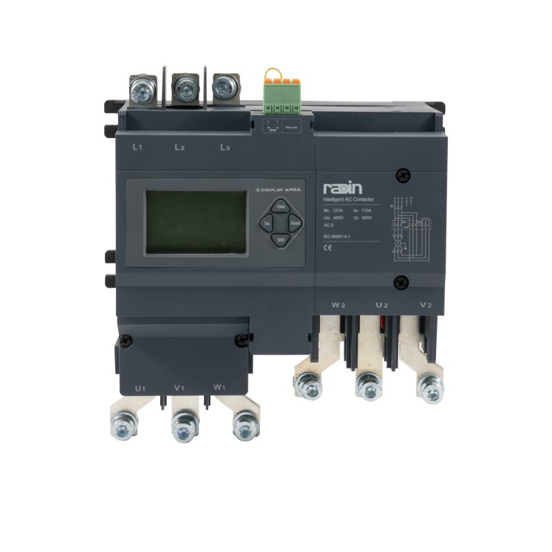
The control circuit dictates how a machine behaves under normal and abnormal conditions. Understanding the difference between core control configurations is vital for matching the hardware to the operational safety requirements of the facility.
Control circuits generally fall into two categories: two-wire and three-wire systems. The terminology refers to the number of wires required to connect the pilot device to the starter enclosure.
A two-wire control circuit utilizes maintained contact devices. Common examples include float switches in pump tanks, pressure switches on air compressors, and thermostats in HVAC units. The diagram shows a simple series circuit: power flows through the switch directly to the contactor coil. When the switch closes, the motor starts. When it opens, the motor stops.
The safety consideration for a two-wire circuit is its automatic restart behavior. If facility power is lost while the switch is closed, the motor will stop. The moment power is restored, the motor will immediately and automatically restart. This is acceptable for an unmanned sump pump, but highly dangerous for a conveyor belt or a lathe where an operator might be clearing a jam when the power returns.
A three-wire control circuit utilizes momentary contact devices, typically Start and Stop push buttons. The diagram is more complex, incorporating the seal-in auxiliary contact discussed earlier. When power is lost, the contactor coil drops out, and the seal-in contact opens. When facility power is restored, the motor will not restart automatically. The circuit remains broken until a human operator physically presses the Start button again. This behavior provides essential undervoltage protection, safeguarding operators from unexpected machine startups after power outages.
Feature | Two-Wire Control | Three-Wire Control |
|---|---|---|
Pilot Device Type | Maintained contact (Float switch, thermostat) | Momentary contact (Push buttons) |
Automatic Restart | Yes. Restarts immediately upon power restoration. | No. Requires manual intervention to restart. |
Primary Application | Unmanned, automated processes (Pumps, compressors) | Operator-driven machinery (Saws, conveyors, lathes) |
Wiring Complexity | Low. Simple series loop. | Moderate. Requires a parallel seal-in circuit. |
Many industrial processes require both local manual control for maintenance and automated control for normal production. This is achieved by integrating a Hand-Off-Auto (HOA) selector switch into the wiring diagram.
The schematic for an HOA circuit splits the control voltage into two parallel paths. The selector switch acts as the gatekeeper. When turned to the Hand position, the switch routes control voltage through a local push-button station, allowing a technician to jog or run the motor manually while standing at the equipment. When turned to the Auto position, the switch routes the voltage through an automated set of contacts. These contacts are typically controlled by a Programmable Logic Controller (PLC), a remote relay, or environmental sensors. The Off position breaks both paths, ensuring the motor cannot run regardless of PLC commands or button presses. This setup is standard in municipal water treatment plants and large-scale manufacturing lines.
Theoretical knowledge of a wiring diagram must translate into precise physical execution. Proper installation practices ensure the longevity of the hardware and the safety of the facility. A sloppy panel layout leads to electrical noise, overheating, and impossible troubleshooting scenarios.
Executing a basic motor starter installation requires a methodical approach. Haphazard wiring leads to crossed phases and control failures. Follow a sequential breakdown to ensure accuracy.
Isolate and Verify: Ensure all incoming power is disconnected at the main breaker. Use a reliable multimeter to verify zero voltage across all phases before opening the panel door.
Mount the Hardware: Secure the DIN rail to the backplate and snap the contactor and overload relay into place. Ensure there is adequate spacing for heat dissipation.
Land the Main Power Lines: Strip the incoming supply wires to the manufacturer's specified length. Insert them into terminals L1, L2, and L3 on the top of the contactor. Ensure no stray copper strands remain outside the lug.
Connect the Motor Leads: Route the wires from the motor into the panel. Land them securely on terminals T1, T2, and T3 at the bottom of the overload relay.
Wire the Control Transformer: If using a CPT, wire the primary side to two of the incoming phases (e.g., L1 and L2). Wire the secondary side to establish your 120V or 24V control power. Ground the secondary neutral.
Wire the Overload Protection: Route the hot control wire through the 95 and 96 NC contacts on the overload relay. This ensures that if the overload trips, it breaks the entire control circuit immediately.
Finalize Push-Button Connections: Run the wiring from the overload relay to the Stop button, then to the Start button, and finally to the A1 terminal on the coil. Connect the A2 terminal to the neutral line. Wire the 13/14 auxiliary contacts in parallel with the Start button to create the holding circuit.
A schematic shows the path of electricity, but it does not dictate the size of the components. Extracting load requirements from the motor nameplate is mandatory. You must identify the Full Load Amperage (FLA), voltage, and phase configuration before cutting a single wire.
Use this data to specify the correct American Wire Gauge (AWG) or metric wire size. Undersized wires will overheat, melt their insulation, and cause panel fires. The contactor must be sized according to its utilization category. The overload relay must be adjustable to encompass the motor's specific FLA. Setting the overload dial incorrectly either causes nuisance tripping or allows the motor to burn up.
Technicians must utilize manufacturer reference charts for terminal torque specifications. A loose connection is a high-resistance connection. High resistance generates heat, which destroys components and causes electrical fires. Always use a calibrated torque screwdriver to tighten lugs to the exact inch-pound specification listed on the hardware. Hand-tightening with a standard screwdriver is unacceptable in industrial environments.
Even experienced technicians make mistakes when translating complex schematics. Identifying frequent errors accelerates troubleshooting and prevents equipment damage during the initial startup phase.
Symptom | Common Wiring Error | Mitigation Strategy |
|---|---|---|
Motor runs only while holding the Start button. | Seal-in contact (13/14) is not wired in parallel, or wired to an NC contact instead of NO. | Verify parallel wiring across the Start button. Check continuity of the auxiliary contact. |
Contactor chatters loudly and fails to pull in completely. | Control voltage is dropping too low during coil inrush, or the CPT is undersized. | Measure voltage at A1/A2 during startup. Upsize the control transformer if voltage drops below 85%. |
Overload trips, but the motor keeps running and smoking. | The 95/96 NC overload contact was not wired in series with the contactor coil. | Rewire the control circuit so the hot leg passes through 95/96 before reaching the push buttons. |
Motor spins backward. | Two of the three power phases are swapped at the motor or contactor. | Swap any two power leads (e.g., T1 and T2) to reverse the magnetic field rotation. |
To mitigate these errors, implement a strict pre-energization checklist. Before applying high voltage, use a multimeter set to continuity mode. Ring out the circuit by physically tracing the schematic line by line, verifying that every point-to-point connection matches the diagram exactly. Check for proper grounding of the enclosure and the motor chassis.
Executing a wiring diagram is a legal and safety obligation. Adherence to the National Electrical Code (NEC) in North America, or IEC standards globally, is non-negotiable. These codes dictate wire ampacity, conduit fill ratios, and short-circuit current ratings (SCCR). Failing to meet these standards results in failed inspections and severe liability.
Strict Lockout/Tagout (LOTO) procedures must be enforced during the wiring process. Never assume a panel is dead just because the machine is quiet. Arc flash considerations must be taken into account during initial testing. When energizing a newly wired panel for the first time, personnel must wear appropriate Personal Protective Equipment (PPE) and stand clear of the blast radius in case a dead short was inadvertently wired into the power circuit.
Selecting the correct hardware requires aligning the facility's operational needs with the capabilities of specific starter configurations. A structured decision framework prevents over-engineering simple systems and under-protecting critical infrastructure.
Before purchasing hardware, define the strict operational requirements of the application. Evaluate the motor size and its load characteristics. Is it a high-inertia load like a massive industrial fan, or a low-inertia load like a small centrifugal water pump? Determine the duty cycle. A motor that starts once a day requires different hardware durability than a motor that jogs fifty times an hour. Assess the available panel space. Retrofitting older enclosures often demands compact hardware solutions. Understanding these metrics is required before selecting a general motor starter for your facility.
Match the physical hardware features to your defined success criteria to ensure optimal performance and safety across the plant floor.
Simple, Isolated Loads: For standalone equipment like small shop grinders or exhaust fans, manual starters are the most efficient choice. They provide essential switching and basic overload protection without the complexity of a secondary control circuit.
High-Inertia Loads on Sensitive Grids: Large chillers, heavy conveyors, and massive blowers draw massive inrush currents that can dim facility lights and trip main breakers. Match these applications to star-delta starters. The reduced voltage starting profile protects the mechanical drivetrain from snapping belts and shields the electrical grid from severe voltage drops.
Critical Process Motors: For motors driving essential manufacturing processes where unexpected downtime ruins product batches, specify starters with comprehensive integrated protection. These units offer precise phase loss detection and rapid short-circuit clearing, ensuring that a motor fault does not escalate into a panel fire.
To ensure a successful installation and reliable motor operation, execute the following steps:
Audit your motor nameplate data to determine the exact full load amperage, voltage, and phase requirements before selecting hardware.
Map out your physical panel space to ensure the selected contactor, overload relay, and control transformer fit within the manufacturer's clearance tolerances.
Verify your control voltage source and install a step-down transformer if your pilot devices require 24VDC or 120VAC for operator safety.
Torque all power and control terminals to the manufacturer's specified inch-pound ratings using a calibrated tool to prevent high-resistance thermal failures.
A: The power circuit carries high voltage and high current directly from the supply lines to the motor to perform the physical work. The control circuit operates at a lower, safer voltage. It handles the logic, utilizing push buttons, timers, and relays to dictate when the power circuit's main contacts open or close.
A: You map them by matching standardized alphanumeric labels stamped on the hardware. The contactor coil symbol corresponds to physical terminals A1 and A2. Normally Open (NO) auxiliary contacts are labeled 13/14, and the thermal overload relay's Normally Closed (NC) trip contacts are marked 95/96.
A: NO (Normally Open) symbols look like two parallel lines with a gap; they block current flow until actuated. NC (Normally Closed) symbols have a diagonal line connecting the parallel lines; they allow current to flow continuously until actuated, at which point they break the circuit.
A: A three-wire circuit uses momentary push buttons and a seal-in contact. If facility power is lost, the circuit breaks. When power returns, the motor will not restart automatically; it requires a human to press the Start button. This undervoltage protection prevents unexpected and dangerous machine startups.
A: The seal-in contact, typically a NO auxiliary contact labeled 13/14, is wired in parallel with the Start button. When the coil energizes, this contact closes, providing an alternate path for the control current. This keeps the coil energized and the motor running after the operator releases the momentary Start button.
A: A DOL starter hits the motor with full voltage immediately, causing a massive inrush current and mechanical shock. A star-delta starter initially applies reduced voltage, lowering the starting current and torque to one-third. This protects sensitive mechanical drivetrains and prevents facility voltage dips during startup.