
- All
- Product Name
- Product Keyword
- Product Model
- Product Summary
- Product Description
- Multi Field Search
Views: 0 Author: Site Editor Publish Time: 2026-09-23 Origin: Site


High-voltage direct current generated by solar photovoltaic arrays presents unique electrical challenges. The main issue is the tendency for direct current to sustain continuous electrical arcs when circuits break. Unlike alternating current, direct current never crosses a zero-voltage threshold. This constant pressure means an electrical arc easily bridges an air gap if you interrupt a live circuit improperly.
Disconnecting a live solar array under load without proper mechanical intervention risks catastrophic arc flashes. This destroys equipment and creates severe safety hazards for maintenance personnel. Standard AC switches are structurally inadequate for DC applications because they lack the internal mechanisms required to extinguish sustained plasma arcs.
Mitigating these risks requires a purpose-built Isolator switch. This guide breaks down the internal mechanics of DC isolation, evaluates specific component architectures, and provides a framework for specifying the correct switch for commercial, residential, and off-grid PV systems.
Arc Suppression is Critical: A true DC isolator switch utilizes specialized spring-loaded mechanisms and magnetic arc chutes to extinguish sustained DC arcs in milliseconds.
Load-Breaking Capability is Mandatory: Safe inverter and battery maintenance requires switches rated to interrupt current flow while the system is actively generating power, unlike non-load-break disconnects.
Component Selection Dictates Safety: Choosing between standard disconnects, an RDGL load isolator switch, or an RDGLR fuse isolation switch depends on whether the system requires integrated overcurrent protection alongside isolation.
Topology Dictates Placement: Complex systems require multi-point isolation, including array-to-inverter, battery-to-charge-controller, and independent isolation for multi-controller bus bar configurations.
Code Compliance vs. Practical Safety: While Rapid Shutdown Devices (RSD) manage module-level voltage, physical isolator switches remain necessary for zero-voltage verification during localized equipment servicing.
Understanding electrical isolation requires looking at the physics of direct current. Alternating current oscillates, crossing zero volts fifty to sixty times per second depending on the grid frequency. This natural zero-crossing momentarily starves an electrical arc of voltage. Standard AC switches rely on this natural drop to extinguish arcs easily. Direct current operates differently. It pushes continuous voltage and never crosses zero. When you open a live DC circuit, the current ionizes the surrounding air and continues flowing as a superheated plasma arc. This plasma can reach temperatures high enough to melt copper contacts and ignite plastic housings instantly.
To combat this continuous pressure, a DC switch utilizes snap-action spring mechanisms. When an operator turns the handle, they are not directly moving the contacts. Instead, they wind torsion springs inside the housing, storing kinetic energy. A mechanical cam holds the contacts closed until the spring reaches a specific tension threshold. Once the handle passes this point, the cam releases. The springs force the internal copper contacts to separate violently. This mechanical separation happens in milliseconds, far faster than human hand speed. Rapid separation minimizes the initial duration and heat of the arc.
Speed alone cannot defeat high-voltage DC. The switch also relies on magnetic arc chutes and chambers. These physical structures sit inside the switch housing and contain stacked, isolated metal plates. As the arc forms between the separating contacts, internal magnetic fields push the plasma arc into these chutes. The plates stretch, cool, and split the single massive arc into dozens of smaller arcs. This process increases the overall resistance of the arc path until the system voltage can no longer bridge the air gap. The arc collapses, and the circuit breaks safely.
The sequence of arc extinction happens in four distinct phases:
Contact Separation: The spring mechanism releases, pulling the copper contacts apart and drawing the initial plasma arc.
Magnetic Deflection: Permanent magnets or the arc's own electromagnetic field forces the plasma outward toward the arc chute.
Arc Splitting: The plasma hits the stacked steel plates, dividing into multiple smaller arcs with higher combined resistance.
Thermal Cooling: The metal plates absorb the heat, dropping the plasma temperature below the ionization threshold, extinguishing the current flow.
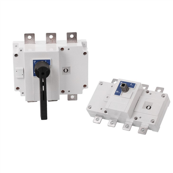
System designers navigate several physical configurations when selecting isolation components. The architecture of the switch dictates its footprint, maintenance schedule, and integration capabilities on the job site. You must match the physical build of the switch to the environment where it will operate.
The primary division in the field lies between rotary mechanisms and knife-blade mechanisms. Rotary switches are compact, fully enclosed, and operate via a twisting dial. You commonly find them integrated into modern string inverters or mounted on DIN rails inside combiner boxes. Their enclosed nature protects the internal contacts from dust, moisture, and oxidation. Traditional knife-blade disconnects offer a visible break. Operators can physically look inside the box and see that the copper blades have left the jaws, confirming the circuit is open. However, knife-blade switches require a much larger footprint. They also demand more frequent maintenance to keep the exposed copper contacts free of corrosion and pitting.
Mounting configurations dictate how you route your conduit and pull your wire. Standalone weatherproof enclosures are necessary for exterior array mounting. These housings protect the switch from rain, snow, and ultraviolet degradation. You mount these directly to the racking system or the exterior wall. Conversely, DIN-rail mounted switches integrate directly into indoor combiner boxes. This allows for a cleaner, centralized wiring layout inside a climate-controlled electrical room.
Complex configurations often involve systems with three or more charge controllers feeding a single massive battery bank. In these setups, a DC PV switch disconnector integrates with heavy-duty copper bus bars. This architecture allows operators to isolate specific controllers independently. You can shut down one charge controller for firmware updates, wire tightening, or component replacement without taking the entire distribution block offline. The rest of the array continues harvesting solar energy.
Architecture Type | Primary Advantage | Common Application | Maintenance Requirement |
|---|---|---|---|
Enclosed Rotary Switch | Compact footprint, IP66 weather resistance | String inverters, outdoor array disconnects | Low. Occasional torque checks on terminals. |
Knife-Blade Disconnect | Visible physical break for LOTO compliance | Utility-scale installations, legacy systems | High. Requires contact greasing and cleaning. |
DIN-Rail Mounted | Seamless integration into existing panels | Indoor combiner boxes, multi-controller setups | Low. Protected by the primary enclosure. |
Different zones within a solar installation require different isolation strategies. Manufacturers engineer specific switch types to handle varying combinations of load breaking and overcurrent protection. Using the wrong switch type in a high-amperage zone leads to premature failure.
The RDGL load isolator switch represents a robust, pure load-break architecture. Engineers design these switches for high-cycle manual disconnection under heavy loads. They feature oversized internal contacts capable of repeatedly interrupting high amperage without degrading. You deploy these in main array disconnects and heavy-duty battery bank isolation zones. Lithium iron phosphate (LiFePO4) battery banks can deliver thousands of amps instantly during a dead short. The RDGL handles the massive inrush and break currents safely. Technicians use them to connect or disconnect batteries to chargers under active current without waiting for the system to power down naturally.
For zones requiring both physical isolation and fault protection, the RDGLR fuse isolation switch is the standard choice. This architecture integrates physical isolation mechanisms with replaceable HRC (High Rupturing Capacity) fuse links. It provides manual disconnection capabilities alongside automatic overcurrent protection. If a charge controller fails and creates a short circuit, the fuse blows, severing the connection before the wire insulation melts. The operator then opens the switch handle, ensuring no voltage reaches the fuse carriage. This allows the technician to replace the blown link safely without touching live metal. The trade-offs include a larger physical footprint to accommodate the fuses and specific thermal management considerations, as fuses generate significant heat under heavy continuous loads.
Proper placement of isolation switches is just as critical as the component selection itself. A well-designed system topology ensures that every high-voltage zone can be safely decoupled for maintenance or emergency response.
For grid-tied string inverters, electrical codes mandate isolation directly adjacent to the inverter. This switch separates the high-voltage DC string coming from the roof from the conversion equipment on the wall. If the inverter requires replacement, technicians lock out this switch and work safely without exposure to the live solar array. If the inverter sits more than a few dozen feet from the array, best practices dictate installing a second isolator on the roof near the panels.
Off-grid and mobile configurations present unique risks. Vans, RVs, and marine vessels manage hundreds of volts in compact, vibration-heavy spaces. Constant road vibrations chafe wire insulation over time, creating severe short-circuit risks against the metal chassis. You must isolate the solar panels prior to servicing these mobile electrical bays. Placing a disconnect switch exactly where the solar cables enter the vehicle interior allows owners to kill power before opening any electrical panels or pulling new wire.
Battery to charge controller isolation is another critical zone. DC battery isolator switches allow operators to safely decouple the battery bank from the charge controller or the primary DC load center. A dedicated isolator prevents high-amperage DC arcing during routine battery maintenance, terminal cleaning, or capacity testing.
Specifying the correct switch requires mapping technical specifications directly to the physical realities of your job site. You must calculate electrical parameters accurately to prevent catastrophic failures. Guessing wire sizes or voltage ratings leads to melted enclosures.
Voltage and current sizing dictate the core safety of the switch. You must calculate the maximum system voltage. This involves taking the open-circuit voltage (Voc) of the solar array and adjusting it for the lowest expected ambient temperature. Solar panels produce higher voltage in freezing conditions. If you string ten 50V panels together, your baseline is 500V. At -10°C, that voltage might spike to 575V. If you install a switch rated for only 500V, the cold-weather voltage spike will arc across the internal contacts and destroy the switch. You must also calculate the maximum short-circuit current (Isc) and multiply it by 1.25 for continuous load, then again by 1.25 for a safety margin. Undersizing leads to fires. Oversizing adds unnecessary cost and physical bulk.
Environmental ratings determine the housing requirements. Outdoor installations require robust protection against UV radiation and moisture ingress. You need IP66 or NEMA 4X enclosures for anything mounted on a roof or exterior wall. Indoor installations allow for simpler IP20 enclosures mounted inside existing metal cabinets.
Compliance and certifications validate the engineering of the switch. You must verify that the component holds IEC 60947-3 and UL 508i or UL 98B certifications. These standards ensure the switch is legally compliant and insurance-approved specifically for DC photovoltaic applications. Using uncertified, generic switches voids equipment warranties and creates massive liability if a fire occurs.
Specification Category | Key Parameters | Application Context |
|---|---|---|
Electrical Sizing | Temperature-adjusted Voc, Isc | Determines the maximum arc suppression capability. Must exceed array maximums. |
Environmental Rating | IP66/IP67, NEMA 4X, IP20 | IP66/NEMA 4X for outdoor array mounting. IP20 for indoor climate-controlled combiner boxes. |
Certifications | IEC 60947-3, UL 508i, UL 98B | Mandatory for legal compliance, grid interconnection approval, and insurance validity. |
Mechanism Type | Rotary, Knife-Blade, Fused | Rotary for compact inverters. Fused for combined overcurrent protection. |
Even the highest-quality switches fail if installed improperly. System designers and installers must address common points of failure in field installations to ensure long-term reliability.
The industry currently debates the role of Rapid Shutdown Devices (RSD) versus physical isolators. RSDs stop power production at the panel level, ensuring emergency responder safety during a fire. They drop the array voltage to safe levels within seconds. However, RSDs are solid-state electronic devices. They can fail. They do not replace physical isolation. A physical DC rated switch remains absolutely necessary. It manages residual voltage trapped in long conduit runs. It also provides a verifiable, visible air gap for maintenance personnel working on the inverter. You can apply a physical padlock to an isolator switch for Lockout/Tagout (LOTO) compliance. You cannot padlock a solid-state RSD signal.
Thermal expansion and improper terminal torquing cause the vast majority of isolator switch fires. Copper wires expand and contract daily as current heats them and nightfall cools them. This thermal cycling loosens terminal screws over time. Loose connections create high electrical resistance. High resistance generates massive heat that melts the switch housing and ignites the surrounding wire insulation. Installers often use impact drivers to tighten terminals, which strips the threads or leaves them deceptively loose. You must mandate the use of calibrated torque screwdrivers during installation. Check the manufacturer's spec sheet for the exact Newton-meter (Nm) rating. Schedule routine thermal imaging inspections to identify hot spots before they ignite.
Condensation and water ingress threaten outdoor enclosures. Even IP67-rated enclosures draw in water through capillary action in the conduit. Warm air inside the conduit hits the cold switch box during the evening, creating internal condensation. Water pools at the bottom of the switch, eventually shorting out the live contacts. You must install proper breather valves or weep holes on the bottom of outdoor enclosures. Always create drip loops in the conduit routing to force gravity to pull water away from the switch entry points.
Follow these field-tested steps when terminating wires inside an isolator switch:
Strip the wire insulation to the exact length specified by the switch manufacturer to prevent exposed copper outside the terminal block.
Apply anti-oxidant joint compound to the exposed copper strands, especially in humid or marine environments.
Insert the wire fully into the terminal lug, ensuring no stray strands sit outside the compression plate.
Tighten the terminal screw using a calibrated torque wrench to the exact specification listed on the device label.
Wiggle the wire vigorously, then re-torque the screw to account for initial strand settling.
Audit your system's single-line diagram to identify all necessary isolation points between arrays, inverters, and battery banks.
Calculate your temperature-adjusted open-circuit voltage (Voc) and short-circuit current (Isc) to properly size your components for worst-case scenarios.
Torque all terminal connections using a calibrated tool and mark them with a paint pen for future visual inspection.
Verify all selected switches carry the appropriate IEC or UL certifications specifically for DC photovoltaic use.
Install breather glands and conduit drip loops on all exterior enclosures to prevent condensation buildup and water ingress.
A: No. AC switches lack the magnetic arc chutes and rapid-break spring mechanisms required to extinguish direct current arcs. AC voltage naturally crosses zero, self-extinguishing arcs. DC voltage provides continuous pressure. Using an AC switch on a DC solar load results in sustained plasma arcing, melted copper contacts, and a severe fire hazard the moment you attempt to open the live circuit.
A: A load break switch safely interrupts the electrical circuit while current actively flows. It contains specialized internal arc suppression components. This allows technicians to disconnect live solar panels or battery banks under full load without damaging the switch contacts, melting the housing, or endangering the operator with arc flashes.
A: You must install DC isolators at multiple strategic points. Place one directly adjacent to the solar inverter to separate it from the incoming roof array. Install another at the solar array itself if the panels sit far from the inverter. Finally, place dedicated isolators between the battery bank and the charge controller.
A: Yes. Isolating individual charge controllers from a common DC bus bar allows for targeted, safe maintenance. You can power down and service a single charge controller without taking the entire solar array offline. This ensures the rest of your system continues to generate and store power while you work.
A: Yes. Rapid Shutdown Devices stop power production at the solar module level primarily for emergency responder safety during fires. However, a physical DC isolator switch remains necessary to manage residual voltage in long conduit runs and provide a verifiable, lockable physical air gap for maintenance personnel servicing the inverter.
A: Improper terminal torquing is the leading cause. Loose wire connections create high electrical resistance, generating extreme heat under load. Other common culprits include water ingress causing internal short circuits, and undersized voltage ratings that fail to suppress electrical arcs during manual disconnection.
A: You test it using a digital multimeter rated for high-voltage DC. Turn the switch to the off position. Measure the voltage across the open outgoing contacts. The multimeter must read exactly zero volts. This confirms the internal mechanical linkage has successfully severed the electrical connection and no voltage is leaking.