
- All
- Product Name
- Product Keyword
- Product Model
- Product Summary
- Product Description
- Multi Field Search
Views: 0 Author: Site Editor Publish Time: 2026-09-15 Origin: Site


Relying solely on nominal horsepower to specify motor control equipment frequently leads to premature contact failure, nuisance tripping, or catastrophic equipment damage. Many technicians use horsepower as a quick shortcut, ignoring critical electrical realities on the factory floor. Incorrectly sized starters create hidden liabilities across your facility. Undersizing risks thermal overload, melted contacts, and unexpected downtime. Oversizing wastes capital expenditure and severely compromises the sensitivity of your overload protection. You need a precise technical framework to get this right.
We evaluate electrical parameters, mechanical load characteristics, and environmental constraints to specify the exact equipment required for safe, compliant, and efficient operation. By prioritizing full load amps and matching your topology to the load dynamics, you eliminate the guesswork. Stop relying on outdated charts and start engineering your motor control circuits with absolute confidence based on hard data and field-tested principles.
Prioritize FLA over Horsepower: Always base your primary sizing calculations on the motor's Full Load Amps (FLA) and system voltage, using horsepower only as a secondary baseline.
Match Topology to Load Dynamics: Select the starting method—whether across-the-line, a KS1 star-delta motor starter, or a soft starter—based on the mechanical load's inertia, motor size thresholds, and the facility's inrush current limitations.
Account for Operating Conditions: Duty cycle, service factor, and ambient temperature require strict derating calculations to prevent thermal degradation of the contactor.
Leverage Integrated Protection: For space-constrained or high-fault applications, utilizing an RDCPS motor starter or a dedicated motor control and protection switch streamlines panel design while maintaining strict safety compliance.
Undersizing a starter guarantees failure on the factory floor. The most immediate mechanical risk is contact welding. When an industrial motor starts, it draws a massive inrush current, often referred to as Locked Rotor Amps (LRA). This transient current routinely reaches six to eight times the normal operating level. Undersized contactors lack the physical mass and arc-quenching capabilities to handle this thermal stress. The silver-alloy contacts liquefy and fuse together under the intense heat. When the control circuit de-energizes, the return spring lacks the mechanical force to break the weld. The motor runs continuously, creating a severe safety hazard that requires operators to manually throw the main disconnect.
Thermal overload presents another severe risk to facility uptime. An undersized overload relay trips constantly during normal startup sequences. Maintenance personnel often respond to these nuisance trips by dialing up the trip setting or bypassing the relay entirely. This removes the thermal protection from the circuit. The motor windings then overheat during operation. The Arrhenius equation dictates that every ten-degree Celsius rise above the rated temperature cuts the motor's insulation life in half. You eventually face a complete stator burnout. Undersizing also increases the risk of phase loss. If one contact pole burns away due to inadequate sizing, a three-phase motor single-phases. It draws excessive current on the remaining two legs, destroying the motor within minutes.
Engineers often oversize starters to play it safe, assuming bigger is always better. This creates a different set of operational problems. Oversizing requires unnecessary capital expenditure. Larger contactors demand more physical panel space. You end up paying for oversized enclosures, heavier gauge wiring, and larger conduit runs. This wastes valuable real estate in crowded electrical rooms and inflates the project budget without delivering tangible benefits.
More importantly, oversizing severely reduces protection sensitivity. Thermal overload relays have specific, narrow adjustment ranges. If you install a Size 3 starter on a motor that only requires a Size 1, the overload relay cannot accurately detect minor fault currents. A slight overcurrent condition—perhaps caused by a failing bearing or a slightly jammed conveyor—will go completely unnoticed. The motor slowly cooks while the oversized relay registers normal operation. The concept of future-proofing a panel by oversizing components is a dangerous misconception. You trade immediate electrical safety for hypothetical future convenience.
Sizing Error | Primary Failure Mechanism | Operational Consequence | Financial Impact |
|---|---|---|---|
Undersizing Contactor | Contact welding during inrush | Inability to stop motor safely | High (Equipment replacement, downtime) |
Undersizing Overload | Nuisance tripping during startup | Operator bypass, motor burnout | High (Motor rewinding/replacement) |
Oversizing Contactor | Excessive physical footprint | Crowded panels, difficult wiring | Medium (Wasted capital expenditure) |
Oversizing Overload | Loss of fault sensitivity | Undetected mechanical binding | High (Premature motor failure) |
Nameplate Full Load Amps (FLA) is your definitive sizing metric. Horsepower only describes the mechanical output at the shaft. FLA describes the actual electrical current required from the grid to do that work. Sizing equipment based solely on horsepower and voltage is insufficient and leads to inaccurate overload relay calibration.
Motors with identical horsepower ratings routinely draw different currents based on their internal design. High-efficiency motors (IE3 and IE4 classes) have significantly lower rotor resistance than older models. They run cooler and save energy, but they draw much higher transient inrush currents than older IE2 motors. A 50HP IE2 motor might draw 300 amps on startup, while a 50HP IE4 motor might spike to 450 amps. If you size a contactor using an outdated horsepower chart, the IE4 motor will weld the contacts on the very first start. Always read the physical motor nameplate. Use the exact FLA value to select your contactor and calibrate your thermal overloads.
You must differentiate starter requirements based on the power supply. Single-phase motors require different handling than three-phase motors. Three-phase motors use all three poles of a standard contactor. Single-phase motors only need two poles. However, you cannot simply leave one pole empty on a modern three-phase starter.
Modern overload relays feature phase-loss sensitivity. They use three bimetallic strips to monitor the current. If they detect zero current on one pole, they assume a phase has dropped and trip immediately to protect the motor. To use a three-phase starter on a single-phase load, you must loop the wire. Route the line voltage through pole L1 and out T1 to the motor. Route the return wire through L2, out T2, loop it back into L3, and out T3 to the neutral. This wiring technique balances the current and heat across all three bimetallic strips, preventing nuisance tripping.
You must evaluate two separate voltage ratings when specifying a starter. The line voltage powers the motor itself. The coil voltage powers the contactor's electromagnet. They are rarely the same. A heavy industrial motor might run on 480VAC, while the control circuit operates on 24VDC or 120VAC for operator safety. Applying line voltage to a low-voltage coil destroys the starter instantly.
You must also account for voltage drop during startup. Weak electrical grids struggle when large motors start. The massive inrush current pulls the system voltage down. If the control transformer is undersized, a 120VAC control circuit might drop to 85VAC. At this low voltage, the contactor coil loses its magnetic grip. The contacts open, the voltage recovers, the coil pulls in again, and the cycle repeats. This rapid chattering creates severe arcing and destroys the starter contacts in seconds. Ensure your control transformer and wire gauge can maintain coil voltage during the heaviest starting conditions.
Service Factor indicates a motor's built-in overload capacity. A 1.15 SF means the motor can handle 15% more than its rated horsepower continuously without damaging the insulation. You must adjust your overload relay settings based on this factor. For a 1.15 SF motor, set the relay to 125% of the nameplate FLA. For a 1.0 SF motor, set it to 115%. Never exceed these multipliers, or you risk thermal damage.
Duty cycle dictates the mechanical wear on the contactor. Continuous duty applications are easy on equipment. The contactor closes once in the morning and stays closed all day. Jogging and plugging applications are brutal. Jogging involves rapid, repeated starts to position a load, like a crane hoist. Plugging involves reversing the motor while it is running to brake it quickly. These actions subject the contacts to massive, repeated arcing. You must heavily upsize the contactor for high-frequency jogging applications to prevent premature failure.
Many technicians confuse basic contactors with complete starters. A contactor only handles the physical switching of the power lines. It uses an electromagnetic coil to close the power contacts. It offers zero protection against overcurrent conditions. If the motor jams, the contactor will happily supply locked-rotor current until the windings melt into slag.
A complete motor starter integrates overload protection. It pairs a contactor with a thermal or electronic overload relay. The relay continuously monitors the current flowing to the motor. If the current exceeds safe limits for a specific duration, the relay opens a normally closed contact in the control circuit. This drops the contactor coil and stops the motor safely. You must always specify a complete starter for motor loads, never just a contactor.
Across-the-line starters are the most common topology in industrial facilities. They connect the motor directly to the full line voltage immediately upon closing. They are simple to wire, highly reliable, and inexpensive. We recommend them for low-inertia loads and robust electrical grids. They work perfectly for small fractional to mid-range horsepower motors driving standard centrifugal pumps.
The trade-offs are significant for larger equipment. Direct-on-line starting applies maximum mechanical stress to belts, gears, and couplings, often shearing pins or snapping belts. It also generates the highest possible inrush current, spiking up to eight times the FLA. Many utility companies strictly prohibit across-the-line starting for motors over 50 horsepower to prevent grid destabilization. You must identify your local utility thresholds before specifying this topology.
Large motors require reduced-voltage starting to protect the mechanical drivetrain and the electrical grid. A KS1 star-delta motor starter provides an excellent electromechanical solution. It requires a motor with six leads. The starter initially connects the windings in a star (wye) pattern. This applies only 58% of the line voltage to each winding. The starting current and torque drop to approximately one-third of direct-on-line values.
Once the motor reaches running speed, a pneumatic or electronic timer switches the contactors. The windings reconnect in a delta pattern, applying full power. You must evaluate the open-transition torque spike. When the contactors switch from star to delta, power drops momentarily. The sudden out-of-phase reconnection can jolt mechanical drivetrains violently. This topology is ideal for centrifugal pumps, large fans, and unloaded compressors. It struggles with high-friction loads like loaded conveyors that require high starting torque.
Solid-state control offers precise ramp-up profiles. Soft starters use silicon-controlled rectifiers (SCRs) to chop the AC waveform, gradually increasing the voltage supplied to the motor. This eliminates mechanical shocks and electrical spikes entirely. You justify the higher cost of solid-state control when dealing with fragile products on a conveyor or strict utility inrush limits.
Soft starters generate significant heat during operation because the SCRs resist current flow. You must manage heat dissipation carefully inside the enclosure. Most modern units include an integrated bypass contactor. Once the motor reaches full speed, the bypass contactor closes. This routes the current around the SCRs, eliminating heat generation during continuous operation. Variable Frequency Drives (VFDs) offer similar starting benefits but add continuous speed control at a much higher price point.
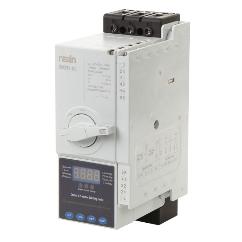
Modern panel design demands extreme space efficiency. The Rapidot architecture revolutionizes layout strategies. An RDCPS motor starter combines multiple discrete functions into a single, compact unit. It integrates the main disconnect isolation, short-circuit protection (magnetic trip), and motor control (thermal trip) into one device. You no longer need to wire separate fuses, disconnect switches, and contactors in series.
This integration drastically reduces the panel footprint, allowing you to fit more motor controls into a smaller enclosure. It simplifies wiring, cuts installation time in half, and reduces the number of potential failure points at the terminals. It also vastly improves short-circuit current ratings (SCCR). The internal components are engineered and tested to work together flawlessly during a massive fault. This architecture is perfect for space-constrained environments and high-density motor control centers.
The National Electrical Manufacturers Association (NEMA) prioritizes robustness and simplicity. NEMA starters use standardized sizes ranging from Size 00 to Size 9. Each size covers a broad horsepower range. A Size 1 starter easily handles anything from 1 to 10 horsepower at 480V. You do not need to calculate the exact amperage to select a NEMA starter.
NEMA designs rely on physical mass to dissipate heat and survive abuse. They feature heavy copper contacts, large arc chutes, and massive coils. They are highly forgiving of operational errors and unexpected overloads. We specify NEMA equipment for heavy industrial environments like steel mills, rock quarries, and lumber mills. They excel where exact load parameters fluctuate wildly and maintenance conditions are rough.
The International Electrotechnical Commission (IEC) prioritizes precision, modularity, and space efficiency. IEC starters do not use broad size categories. They use highly granular sizing based on precise utilization categories. An AC-3 rating applies to standard squirrel-cage motors starting and stopping. An AC-4 rating applies to brutal jogging and plugging applications.
IEC starters are physically smaller and less expensive than NEMA equivalents. They achieve this through advanced metallurgy and superior arc chute design rather than raw mass. However, they offer zero reserve capacity. You must calculate the load perfectly. If you undersize an IEC starter by even a few amps, it will fail quickly under load. They require strict adherence to design limits and are favored by OEM machine builders looking to save space.
IEC designs heavily favor modularity on DIN rails. Engineers frequently utilize manual motor protectors (MMPs) in tandem with contactors. A dedicated motor control and protection switch provides fuseless short-circuit and overload protection. You mount it directly above the contactor, linking them with a solid busbar.
This combination creates a highly compact, perfectly coordinated motor branch circuit. If a fault occurs, the switch trips and isolates the contactor instantly. You simply clear the fault and reset the rotary switch to restore power. There are no blown fuses to hunt down and replace. This modular approach dominates modern machine building and automated panel design.
Feature | NEMA Standard | IEC Standard |
|---|---|---|
Sizing Methodology | Broad horsepower ranges (Size 00 to 9) | Exact amperage and utilization category |
Physical Footprint | Large, heavy, requires more panel space | Compact, modular, saves panel space |
Reserve Capacity | High reserve; highly forgiving of overloads | Zero reserve; requires precise calculation |
Primary Use Case | Heavy industry, variable unpredictable loads | OEM machinery, space-constrained panels |
Maintenance | Contacts and coils easily replaceable | Often replaced as a complete unit |
The operating environment dictates your enclosure selection. You must select the correct NEMA rating to protect the internal equipment. NEMA 1 is strictly for clean, dry indoor areas. NEMA 3R handles outdoor rain and ice. NEMA 4X resists high-pressure washdowns and corrosive chemicals in food processing plants. NEMA 12 blocks industrial dust and oil drips in machining centers.
Placing a starter inside a sealed enclosure traps heat. The contactor coil and overload relay generate significant thermal energy during operation. You must calculate the internal heat rise. If the ambient temperature outside the box is high, the inside will bake. You must apply thermal derating factors provided by the manufacturer. A contactor rated for 50 amps in open air might only handle 40 amps inside a sealed NEMA 4X enclosure. Failure to derate leads to melted components and premature failure.
Mechanical load characteristics dictate your overload relay selection. Variable torque loads like centrifugal pumps and small fans spin up quickly. They reach full speed in two or three seconds. A standard Class 10 overload relay works perfectly here. It trips if the inrush current lasts longer than 10 seconds, protecting the motor from a locked rotor.
High-inertia loads behave completely differently. Industrial centrifuges, rock crushers, and massive bandsaws take a long time to accelerate due to their sheer physical mass. They might draw high inrush current for 15 to 25 seconds before reaching running speed. A Class 10 relay will trip prematurely every single time you start the machine. You must specify a Class 20 or Class 30 overload relay for high-inertia loads. These relays allow the extended ramp times required without sacrificing ultimate thermal protection.
Altitude physically changes electrical properties. Air becomes thinner above 1,000 meters (3,300 feet). Thin air is a poor insulator. It reduces the contactor's ability to quench electrical arcs when the contacts open. Thin air also absorbs less heat, meaning the equipment runs hotter than it would at sea level.
You must apply altitude derating formulas. A starter operating at 2,000 meters requires a lower amperage rating and a lower voltage rating to operate safely. Ambient temperature also skews protection. Traditional bimetallic overload relays rely on heat to trip. If the ambient temperature in the electrical room is extremely high, the relay trips too early. If it is freezing outside, it trips too late. You must specify ambient-compensated overload relays or upgrade to solid-state electronic overloads for extreme environments.
Walk up to the physical motor and wipe off the nameplate. Never rely on old drawings.
Extract the Full Load Amps (FLA) for your specific operating voltage.
Record the Phase configuration and the Service Factor (SF).
Note the insulation class and the NEMA design letter to understand the inrush profile.
Evaluate the mechanical load inertia. Does it spin up instantly or take 20 seconds?
Check utility constraints. Will the grid handle a 600% current spike?
Select across-the-line for simple loads, star-delta for large pumps, or soft starters for fragile mechanical systems.
Choose NEMA for heavy, unpredictable industrial environments where maintenance is rough.
Choose IEC for compact, precise machine builds where space is at a premium.
Specify the correct enclosure rating (NEMA 1, 3R, 4X, 12) based on dust, water, and chemical exposure.
Apply thermal derating factors if using a sealed, non-ventilated box.
Calculate the exact trip class required (Class 10, 20, or 30) based on acceleration time.
Multiply the motor's FLA by the correct Service Factor percentage (115% or 125%).
Select an overload relay where this calculated number falls squarely in the middle of its adjustable dial range.
Even perfectly sized equipment fails if installed poorly by the electrical contractor. Loose terminations are the leading cause of field failures in motor control centers. A loose wire creates high electrical resistance at the terminal. This resistance generates intense heat under load. The heat travels down the wire, melts the contactor housing, and destroys the overload relay. You must use a calibrated torque screwdriver on every single terminal, following the manufacturer's exact inch-pound specifications.
Improper grounding creates severe safety hazards and control anomalies. Stray voltage can keep a contactor coil energized even when the control switch is open, causing the motor to run unexpectedly. Voltage drop across undersized control wires causes coil chattering and contact destruction. Mitigate these risks through strict quality control during commissioning. Implement routine thermal imaging inspections under full load. A thermal camera instantly reveals loose connections, unbalanced phases, and overloaded contacts before they cause catastrophic downtime.
Audit all existing motor nameplates in your facility to verify that current starters are sized based on FLA, not just horsepower.
Implement a standardized torque verification program using calibrated tools for all motor control terminations to prevent thermal failures.
Upgrade high-inertia load protection by replacing nuisance-tripping Class 10 relays with appropriate Class 20 or Class 30 overload relays.
Transition space-constrained panels to integrated protection architectures to improve short-circuit current ratings and free up DIN rail space.
Establish a thermal imaging inspection schedule for all motor control centers to detect voltage drop and loose connections before they cause downtime.
A: Yes, you can use a three-phase starter for a single-phase load. However, you must wire the power through all three poles in series. This balances the current across the bimetallic strips and prevents the overload relay from detecting a phase loss and tripping prematurely.
A: Contactor chatter usually indicates a severe voltage drop in the control circuit. When the motor draws high inrush current, the system voltage sags. The coil loses magnetic strength, causing the contacts to bounce rapidly. You need a larger control transformer or thicker control wiring.
A: The class rating dictates the maximum tripping time under locked-rotor conditions. A Class 10 relay trips within 10 seconds. A Class 20 relay allows up to 20 seconds, making it necessary for high-inertia loads like centrifuges that take longer to accelerate.
A: Yes. Sealed enclosures trap heat generated by the contactor coil and power contacts. You must apply the manufacturer's thermal derating factor to prevent the internal components from exceeding their maximum temperature ratings and melting.
A: High-efficiency (IE3/IE4) motors have lower rotor resistance. They draw significantly higher transient inrush currents during startup compared to older motors. You must upgrade the contactor to handle this increased transient current, even if the horsepower is the same.
A: Choose NEMA for heavy industrial environments where loads fluctuate and you need robust reserve capacity. Choose IEC for OEM machinery and tight panel spaces where loads are precisely calculated, predictable, and space is limited.