
- All
- Product Name
- Product Keyword
- Product Model
- Product Summary
- Product Description
- Multi Field Search
Views: 0 Author: Site Editor Publish Time: 2026-08-30 Origin: Site


Unplanned downtime from electrical transients destroys equipment and degrades electronic lifespans. Specifying the correct surge protection device is a strict engineering requirement, yet many facility managers either over-specify components, wasting capital, or under-specify them, creating a false sense of security that ends in system failure. This disconnect happens when installation teams misunderstand equipment classifications, zoning, and alternative power quality hardware. You need a systematic evaluation framework to get this right. Selecting protection depends entirely on facility topology, standard compliance like IEC 61643-11 or UL 1449, and specific application demands. These requirements scale from heavy-duty service entrances down to intricate PCB-level integration. We will break down how to match the exact surge protection class to your operational environment, ensuring transient voltages are intercepted before they breach your equipment thresholds.
Location Dictates Class: Type 1 SPDs handle direct lightning currents at the service entrance, Type 2 manage residual surges at distribution boards, and Type 3 protect sensitive equipment at the point of use.
Cascading is Non-Negotiable: Effective facility protection requires a coordinated, multi-tiered approach rather than relying on a single high-capacity unit.
Form Factor and Function Must Align: Choosing between standard wall-mounted enclosures, DIN rail-mounted configurations, or hybrid T1+T2 surge arresters depends heavily on spatial constraints and discharge requirements.
Component-Level Defense is Evolving: OEM applications increasingly require embedded solutions, making the selection of a reliable 5-PCB mounted surge protector critical for custom hardware longevity.
Defining success criteria for transient mitigation starts at the single-line diagram. The primary goal is intercepting transients before they breach equipment thresholds while maintaining continuous power delivery to critical loads. A properly specified system acts invisibly. It shunts excess energy to ground without interrupting normal operations or tripping upstream breakers. When you walk into a mechanical room, you should see a coordinated defense strategy, not just a random box bolted to the wall.
Specification errors frequently occur when electrical contractors confuse different power quality devices. These components serve distinct operational purposes. You cannot swap them out and expect the same results. Understanding the boundaries of each device prevents catastrophic design flaws.
Device Type | Primary Function | Transient Handling Capability | Limitations |
|---|---|---|---|
Surge Protector | Clamps high-voltage transient spikes | Massive energy dumps (microseconds) | Cannot provide backup power or regulate continuous voltage |
Uninterruptible Power Supply (UPS) | Provides battery backup during outages | Minimal (often relies on basic internal MOVs) | Will fail if hit by a service-entrance level surge |
Power Conditioner | Filters EMI/RFI noise and regulates voltage | Low-level noise and minor fluctuations | Lacks robust components for direct lightning strikes |
Engineers install Type 1 devices before or immediately after the main load center. They sit at the boundary between the utility grid and the facility infrastructure. Their technical function is safely discharging high-energy external surges. Direct lightning strikes on utility poles and massive grid switching events fall into this category. You must size the conductors appropriately, typically using 6 AWG or larger wire, to handle the massive current flow without melting the insulation.
We evaluate these units primarily by their Impulse Current capacity (Iimp). Testing laboratories utilize a 10/350 µs waveform to simulate these events. This specific waveform represents a massive, sustained energy transfer. It takes 10 microseconds to reach peak current and 350 microseconds to decay to half its peak value. Surviving this waveform requires robust internal components. Manufacturers typically use heavy-duty Metal Oxide Varistors (MOVs) or Gas Discharge Tubes (GDTs) with massive thermal capacities. If you install a device rated only for 8/20 µs at the service entrance, a direct strike will blow it off the wall.
You install Type 2 devices downstream from the main breaker. They protect specific branch circuits and sub-panels. Their primary technical function is mitigating internally generated transients. Heavy machinery, variable frequency drives (VFDs), large contactor switching, and HVAC cycling cause these daily spikes. They also handle residual external surges that bypass the Type 1 device.
Evaluation relies on Nominal Discharge Current (In) and Maximum Discharge Current (Imax) ratings. Testing utilizes an 8/20 µs waveform. This represents a shorter, less intense energy spike typical of internal switching events. Type 2 units form the backbone of facility-wide protection. They intercept the majority of daily transient activity before it reaches sensitive zones. You will typically mount these on DIN rails inside the distribution panel, wiring them in parallel with the load to ensure continuous operation even if the protection module degrades.
Type 3 devices sit directly adjacent to sensitive loads. Programmable Logic Controllers (PLCs), server racks, and medical imaging equipment require this close proximity. Their function is providing fine voltage clamping for highly sensitive electronics. They handle the minimal residual energy that escapes upstream protection.
Engineers evaluate them by Open Circuit Voltage (Uoc) using a combination wave. This test applies a 1.2/50 µs voltage wave and an 8/20 µs current wave simultaneously. Type 3 units prioritize a low let-through voltage over massive discharge capacity. They act as the final barrier for critical silicon components. Never install a Type 3 device without upstream protection; it simply does not have the thermal mass to survive a high-energy event.
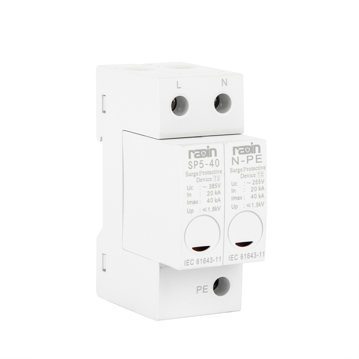
Modern electrical infrastructure often presents severe spatial constraints. Manufacturers continuously combine classes and shrink form factors to solve specific engineering challenges. Understanding these advanced configurations allows for flexible, high-performance system design in tight enclosures.
Technical architecture in hybrid units combines different suppression technologies. They often utilize both Gas Discharge Tubes and Metal Oxide Varistors. GDTs handle massive energy impulses but have slower reaction times and can suffer from follow-on current issues. MOVs react almost instantly but degrade under sustained heavy currents. Combining them leverages the strengths of both components while mitigating their individual weaknesses.
Component Technology | Reaction Time | Energy Capacity | Primary Drawback |
|---|---|---|---|
Metal Oxide Varistor (MOV) | Sub-nanosecond (Very Fast) | Moderate to High | Degrades over time with repeated surges |
Gas Discharge Tube (GDT) | Microsecond (Slower) | Extremely High | Follow-on current can trip upstream breakers |
Hybrid (MOV + GDT) | Sub-nanosecond | Extremely High | Requires complex internal coordination |
This hybrid approach handles high-energy impulses while providing low voltage protection levels (Up). A T1+T2 surge arrester is ideal for compact industrial control panels. Telecommunication base stations and remote pumping stations also benefit greatly. Installing separate Type 1 and Type 2 devices is physically impossible in these tight enclosures. The combined unit ensures full-spectrum protection without expanding the panel footprint. You get the 10/350 µs survivability alongside the 8/20 µs clamping precision.
Original Equipment Manufacturers require protection built directly into their hardware. Miniaturized components designed for direct soldering onto printed circuit boards fulfill this need. Electric vehicle charging modules, smart grid meters, and industrial sensors require integrated transient protection to survive field deployment. You cannot rely on the end-user to install external protection; you must build it into the device.
A reliable 5-PCB mounted surge protector provides localized, component-level defense. When evaluating these modules, engineers must scrutinize specific criteria. Footprint size dictates board layout flexibility. Thermal disconnect mechanisms are mandatory to prevent fire hazards if the MOV degrades over time. Wave soldering compatibility ensures the component survives the automated manufacturing process without internal damage. The pins must align perfectly with standard grid spacings to facilitate rapid assembly on the production line.
Mapping technical specifications to real-world performance outcomes is critical. You cannot rely on marketing claims; you must analyze the engineering data. Compliance standards dictate how these metrics are measured and reported.
Engineers must analyze the fundamental trade-off in transient suppression. High discharge capacity often results in a higher clamping voltage. You must balance maximum discharge requirements (Imax) with the necessary Voltage Protection Rating (Up). Downstream equipment has specific withstand thresholds. Exceeding these thresholds causes immediate silicon degradation or catastrophic failure.
If you select a unit with massive capacity but a high let-through voltage, the transient energy will still destroy the sensitive load. The protection device survives, but the equipment it was meant to protect dies. Careful coordination ensures the clamping voltage remains well below the equipment's susceptibility level. For example, a 277/480V system might require a clamping voltage under 1200V to protect sensitive VFDs downstream.
Global specification accuracy requires understanding overlapping terminology. North American engineers often use IEEE standards, while international projects rely on IEC classifications. Clarifying these metrics prevents costly procurement errors on international builds.
IEEE Category | IEC Standard Equivalent | Application Zone | Surge Characteristics |
|---|---|---|---|
Category C | Type 1 | Service entrance, severe environments | Handles 10kV, 10kA surges (External) |
Category B | Type 2 | Downstream, $\ge$ 30 ft from Category C | Branch circuits, sub-panels (Internal) |
Category A | Type 3 | Point of use | Sensitive electronics (Residual) |
Physical deployment options directly impact installation speed and future maintenance. Standard wall-mounted configurations are ideal for heavy-duty NEMA-rated service entrances. They offer rugged enclosures suited for harsh environments, protecting the internal components from dust and moisture. DIN rail-mounted configurations are optimal for modular sub-panel integration. They snap cleanly into existing control cabinets alongside standard breakers, keeping wire runs short and organized.
Assess the value of pluggable modules versus fixed units. Fixed units require complete replacement and rewiring when they reach the end of their lifespan. This means shutting down the panel, locking it out, and bringing in an electrician. Pluggable cartridges allow maintenance staff to swap degraded modules in seconds without turning off the power. This modularity drastically reduces maintenance downtime and lowers long-term operational expenses in high-surge industrial environments.
Examining how specific product series align with distinct facility needs clarifies the selection process. Different environments generate vastly different transient profiles. A commercial office building does not face the same electrical stress as a heavy manufacturing plant.
Sub-panels in manufacturing plants face aggressive electrical environments. Variable frequency drives, large inductive motors, and automated welding equipment generate constant internal transients. Deploying the SP5-B series T2 class surge protection device addresses these specific operational parameters.
This series features high maximum discharge ratings designed for aggressive industrial environments. Integrated status indicators provide immediate visual feedback on component health. A green flag means operational; a red flag means the internal MOV has degraded and requires replacement. Remote signaling contacts allow seamless integration with Building Management Systems. When a module degrades, the system automatically alerts maintenance personnel, preventing periods of unprotected operation.
Embedding protection directly into proprietary hardware demands strict engineering oversight. You must focus on thermal stability and lifecycle matching. The protection component must outlast the host device or fail safely without causing collateral damage. OEM designers must account for creepage and clearance distances on the PCB. They must also ensure the copper traces can handle the immense current spikes without vaporizing. If the trace is too thin, it acts as a fuse, blowing open during a surge and rendering the protection useless. Engineers must calculate the trace width based on the expected Imax rating of the embedded component.
Devices frequently fail in the field despite correct specification. Physical and electrical installation realities cause these failures. Understanding implementation risks is as important as selecting the right hardware. A perfectly specified unit installed poorly offers zero protection.
A major risk involves installing a Type 3 device without upstream protection. If a massive external surge hits the facility, the Type 3 unit attempts to absorb energy far beyond its design limits. This leads to catastrophic failure, often resulting in localized burning or explosion of the component.
Mitigation mandates a coordinated, cascaded approach. You must maintain proper decoupling distances between zones. The natural inductance of the wiring between the Type 1 and Type 2 devices ensures the upstream unit triggers first. Typically, you need at least 10 meters of wire between a Type 1 and Type 2 device to provide enough inductance. This coordination forces the heavy-duty components to absorb the bulk energy, leaving only manageable residual spikes for downstream units.
Excessive lead lengths completely negate effectiveness. This is the most common installation error globally. Leads over 50 cm introduce severe inductive voltage drop during a rapid surge. The physical formula V = L * di/dt explains this phenomenon. Rapid current changes (di/dt) across the wire's inductance (L) create massive voltage spikes.
If the transient current rises at 10kA per microsecond, a single meter of wire can add thousands of volts to the let-through voltage. Mitigation requires strict installation guidelines. Keep leads as short and straight as possible. Avoid sharp bends or loops, which increase inductance. Furthermore, ensure the facility grounding system measures below required impedance thresholds. A protection device cannot shunt energy to ground if the ground path presents high resistance. Aim for a ground impedance of 5 ohms or less for optimal performance. Test the grounding rods annually to ensure soil degradation hasn't compromised the system.
No single unit can secure an entire facility against transient events. A tiered, class-based approach is a strict engineering requirement. Relying on a single line of defense leaves critical infrastructure vulnerable to both external lightning impulses and internal switching degradation.
The shortlisting logic follows a clear decision matrix. Use Type 1 units for service entrances to handle massive external energy. Specify robust Type 2 units for comprehensive sub-panel defense against internal switching. Utilize hybrid T1+T2 units for space-constrained, high-risk zones. Finally, integrate PCB-mounted modules directly into OEM hardware for localized defense.
Take the following actions to secure your infrastructure:
Audit your current single-line diagrams to identify unprotected distribution nodes and critical loads.
Verify your facility grounding impedance meets strict local electrical code requirements for surge dissipation.
Measure existing lead lengths on installed units and rewire any connections exceeding 50 centimeters.
Consult a technical sales engineer to match exact discharge specifications to your specific load profiles.
A: Installation location and waveform testing define the difference. Type 1 handles 10/350 µs direct lightning currents at the service origin. Type 2 handles 8/20 µs residual surges and internal switching transients at downstream sub-panels.
A: No. It only clamps transient voltage spikes. It does not provide battery backup for power outages like a UPS. It also does not regulate continuous voltage fluctuations or filter line noise like a power conditioner.
A: Specify a combined unit when physical space in the distribution panel is limited. It is necessary when the location still requires robust protection against both direct lightning impulses and standard switching transients.
A: No. Type 3 devices lack the discharge capacity for high-energy surges. They will suffer catastrophic failure if they are not protected by upstream Type 1 and Type 2 devices intercepting the bulk of the transient energy.
A: It is the maximum voltage the device will let through to the connected equipment during a surge event. This clamping voltage must be strictly lower than the downstream equipment's maximum withstand voltage to prevent damage.
A: Integration requires matching the exact PCB footprint. You must ensure adequate copper trace widths to handle high surge currents. Incorporating required thermal disconnect mechanisms per UL and IEC standards is also mandatory for safety.
A: Long or looped wires add parasitic inductance. This creates a massive voltage drop during a rapid surge. It effectively raises the clamping voltage seen by the equipment, severely reducing the actual protection level provided.