- All
- Product Name
- Product Keyword
- Product Model
- Product Summary
- Product Description
- Multi Field Search
Views: 0 Author: Site Editor Publish Time: 2026-05-05 Origin: Site


Selecting a motor starter is never a basic procurement task. It serves as a critical safeguard for your expensive capital equipment. When you specify the wrong device, you invite severe mechanical wear, sudden voltage sags, and crippling unplanned downtime. Electric motors form the heavy-duty backbone of modern manufacturing and infrastructure. In these demanding industrial environments, starter components perform two essential functions. They switch electrical power safely while delivering robust, continuous overload protection. Without them, electric motors simply cannot survive the harsh realities of fluctuating currents and abusive mechanical loads.
Choosing the right mechanism requires a delicate balancing act. You must weigh the initial hardware expenses against highly complex application requirements. Furthermore, you need to evaluate the specific load characteristics of your machinery and the strict electrical compliance standards governing your facility. Read on to discover how to align starter mechanisms with complex load profiles, evaluate major rating systems, and sidestep common installation pitfalls.
Direct-On-Line (DOL) starters offer simplicity but introduce high mechanical stress; Soft Starters provide controlled acceleration to extend equipment lifespan.
Choosing between NEMA and IEC ratings depends on your operational philosophy: NEMA favors robust, general-purpose sizing, while IEC demands precise application matching.
Evaluating industrial control motor starters requires aligning the starter’s thermal and magnetic protection capabilities with your specific load profile (e.g., constant vs. variable torque).
Correct sizing and enclosure selection (IP/NEMA ratings) are non-negotiable for compliance and long-term reliability.
Motor failures carry massive financial consequences for any industrial operation. Rewinding a blown industrial motor consumes thousands of dollars in copper and specialized labor. Beyond direct repair bills, lost production time causes facility revenue to plummet by the minute. To prevent this catastrophic sequence, you rely heavily on Industrial Control Motor Starters. They do much more than simply initiate shaft rotation. They stand as your primary, intelligent line of defense against electrical anomalies.
These devices actively monitor electrical current constantly. When dangerous phase loss happens, a motor pulls excessive current on the remaining phases. This melts delicate winding insulation rapidly. High-quality starters detect this dangerous imbalance immediately. They sever main power instantly to save the equipment. Thermal overloads also constantly threaten heavy machinery. Continuous, minor current overloads degrade internal components over weeks or months. A properly specified Motor Starter tracks this gradual heat buildup accurately.
Success in electrical design depends on several critical criteria. First, you must successfully minimize inrush current to protect the local facility grid from voltage sags. Second, you must match the starter to the physical mechanical load requirements precisely. Finally, you must ensure the device integrates seamlessly into your existing plant control systems and automation networks.
Engineers utilize several fundamental starting methods. Each technology offers distinct advantages and operational risks. You must evaluate the pros, cons, and cost-to-benefit ratios carefully.
Mechanism: They close internal contacts to apply full line voltage directly to the motor terminals instantly.
Evaluation: You achieve the absolute lowest upfront purchase cost. Maintenance teams appreciate them because physical troubleshooting remains straightforward. They consist of simple contactors and basic overload relays.
Risk: You subject the mechanical system to extreme inrush currents. These startup currents routinely hit six to eight times the Full Load Amps (FLA). This massive power draw strains the local electrical grid, causing lights to dim and sensitive electronics to falter. It also delivers a violent mechanical shock to driven belts, couplings, and bearings. You should strictly restrict DOL usage to small water pumps or basic exhaust fans where mechanical shock is negligible.
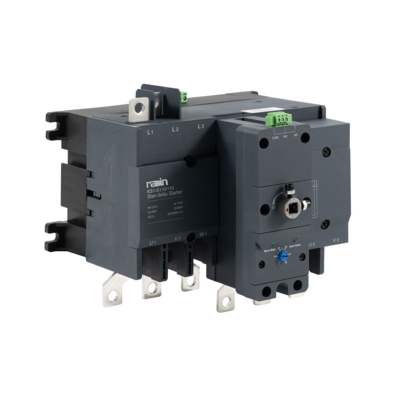
Mechanism: The internal circuitry starts the motor in a star (wye) configuration. This specific wiring strategy reduces the applied voltage and current significantly across the windings. After a predetermined time delay, the contactors switch the wiring to a delta configuration to deliver full running voltage.
Evaluation: You gain a highly cost-effective method for achieving substantial current reduction during the startup phase. It uses traditional electromechanical components, keeping repair costs low.
Risk: You lose substantial starting torque. The physical torque output drops to roughly 33% of normal operating levels. This makes it useless for starting heavy loads. Furthermore, the brief open transition between wiring configurations can trigger damaging electrical transients and current spikes.
Mechanism: These utilize advanced solid-state devices. Internal thyristors or Silicon-Controlled Rectifiers (SCRs) carefully chop the AC voltage waveform. This allows the internal microprocessor to gradually ramp up the voltage sent to the motor terminals over a programmable timeframe.
Evaluation: You completely eliminate harsh mechanical jerks upon startup. This smooth, controlled operation prevents destructive water hammer in commercial plumbing networks. You also gain the advanced ability to program fully adjustable acceleration and deceleration ramp profiles to suit fragile products.
Risk: You must accept a notably higher initial equipment cost. Additionally, operating solid-state components generates continuous heat. You must design proper panel ventilation or install active cooling fans to compensate. Many engineers add an internal bypass contactor to remove the SCRs from the circuit once the motor reaches full speed, thereby reducing internal panel heat.
Starter Type | Initial Cost | Inrush Current | Starting Torque | Best Application |
|---|---|---|---|---|
Direct-On-Line (DOL) | Low | Extremely High (6-8x FLA) | 100% (High Shock) | Small pumps, basic fans |
Star-Delta | Medium | Moderate | Low (~33%) | Unloaded compressors |
Soft Starter | High | Low (Controlled) | Adjustable | Conveyors, complex fluid systems |
Engineers globally debate the merits of NEMA and IEC standards. Both frameworks guarantee operational safety when implemented correctly. However, they approach sizing and deployment from vastly different operational philosophies. Understanding this divide prevents costly specification errors.
The IEC Approach:
IEC-rated components originate from European engineering standards. They are intentionally compact and highly modular to fit into tight control panels. Manufacturers build them to be strictly application-specific. To use them successfully, you must possess exact knowledge of your motor's duty cycle. You must also understand the precise mechanical load characteristics. This granular, optimized approach usually yields a lower upfront hardware cost and saves valuable panel space. However, it leaves absolutely zero margin for sizing errors. If your load unexpectedly increases, an IEC contactor will likely fail prematurely.
The NEMA Approach:
NEMA devices cater to traditional North American industrial demands. They look physically larger and feel heavily robust. Engineers size them by broad horsepower classifications rather than exact operational current limits. This over-engineered design philosophy makes them ideal for harsh, unpredictable environments. When specific load parameters fluctuate, or when plant operators abuse the machinery, NEMA provides a massive safety buffer. You will pay a higher initial cost for this robustness. In return, you gain superior durability under severe mechanical and electrical stress.
Key Sizing Metrics to Verify:
Regardless of your standard preference, you must verify three vital electrical metrics. First, you need the Full Load Amps (FLA) to calibrate the thermal protection devices accurately. Second, you must check the motor's Service Factor (SF) to determine temporary overload capabilities safely. Finally, verify the Short-Circuit Current Rating (SCCR). This ensures the Motor Starter can withstand catastrophic electrical fault conditions without exploding or causing secondary fires.
Selecting hardware based purely on horsepower ratings guarantees failure. Different industrial loads exert entirely unique mechanical demands on the system. Here is how you align your control hardware with physical operational outcomes.
High-Inertia Loads: Machines like large centrifugal blowers, industrial centrifuges, and rock crushers demand massive starting torque. Getting a heavy mass spinning takes significant energy over an extended timeframe. You should use sophisticated soft starters equipped with aggressive current limit features. If your facility grid can handle massive voltage dips without tripping other equipment, heavy-duty NEMA DOL devices might work.
Variable/Fragile Loads: Conveyor belts and glass bottling lines require exceptionally gentle handling. Sudden mechanical jerks ruin products instantly and cause line jams. Soft starters are absolutely mandatory for these fragile applications. They prevent product tipping entirely. They also keep rubber conveyor belts from snapping or slipping off rollers during the crucial acceleration phase.
Fluid & Pumping Systems: Moving heavy liquids creates complex hydraulic forces. These systems require highly controlled deceleration sequences just as much as controlled acceleration. You must utilize specialized pump control profiles programmed into advanced soft starters. This steady deceleration eliminates destructive water hammer in the pipes. It also prevents heavy mechanical check-valves from slamming shut violently and cracking the plumbing.
Environmental Constraints: You must match the enclosure rating strictly to the physical environment. Look at NEMA 1, 12, 3R, or 4X ratings depending on indoor or outdoor placement. Alternatively, use IP65 or IP67 equivalents. This shields your Industrial Control Motor Starters against ambient dust, driving moisture, and corrosive chemical exposure.
Application Type | Primary Challenge | Recommended Solution | Crucial Feature Required |
|---|---|---|---|
Rock Crushers | Massive starting inertia | Heavy-Duty Soft Starter / DOL | Extended current limit capabilities |
Bottling Lines | Product tipping, belt slip | Standard Soft Starter | Linear voltage acceleration ramp |
Municipal Water Pumps | Water hammer, pipe stress | Advanced Soft Starter | Dedicated pump deceleration profile |
Outdoor Conveyors | Weather and dust ingress | Any suitable starter type | NEMA 4X / IP66 rated enclosure |
Real-world deployments often fail due to minor engineering oversights. Avoid these common missteps to ensure long-term electrical reliability and facility safety.
Common Pitfalls:
Ignoring the substantial heat dissipation requirements of solid-state components. Failing to calculate internal thermal loads leads directly to severe panel overheating and microprocessor failure.
Mismatching the overload relay class with the physical load. You must align Class 10, Class 20, or Class 30 relays properly based on the equipment's inertia.
Failing to match the relay to the motor's required starting time. This mistake causes frustrating nuisance tripping during routine, perfectly healthy startups.
The Procurement Checklist (Next Steps):
Follow this standardized, chronological procedure when sourcing your next industrial device:
Verify your facility's internal grid capacity and transformer sizing. You must ensure it can handle massive inrush currents safely without dropping voltage elsewhere.
Confirm all mandatory local compliance requirements. Look specifically for UL, CSA, or CE safety certifications depending on your geographic region.
Evaluate long-term vendor support capabilities thoroughly before purchasing. Consider their engineering documentation and technical support availability.
Ensure the immediate availability of crucial replacement contact kits to minimize downtime during routine maintenance turnarounds.
Check for modular add-ons like snap-on auxiliary contacts. Always review the detailed warranty terms regarding solid-state component lifespans.
Final Verdict: Summarizing the selection process, finding the "best" motor starter remains a strict engineering compromise. You must carefully balance your available maintenance budget against physical mechanical load tolerances. You also need to account for your facility's existing electrical infrastructure limitations. A device that works perfectly for a simple fan will fail catastrophically on a heavy crusher.
Call to Action: We encourage you to audit your current motor failure rates today. Look for mechanical shock damage indicating poor startup control, or burned windings indicating poor overload protection. Consult directly with a qualified application engineer. They will help you precisely size your next industrial control motor starter correctly, ensuring maximum operational reliability and extending your equipment's lifespan.
A: Soft starters only control voltage during the startup and shutdown phases to limit current and mechanical shock. Once running, the motor operates at full speed. VFDs control frequency and voltage to adjust speed and torque continuously throughout the entire operation. Do not pay for a complex VFD if you only need starting control.
A: Yes, but you must account for several panel changes. You need to evaluate the physical footprint difference carefully, as solid-state devices often require more space. Furthermore, you must ensure adequate cooling ventilation to manage the constant heat generated by internal thyristors.
A: You must strictly match it to the motor's specific start time. A Class 10 relay trips in 10 seconds, suiting standard pumps and fans. Class 20 trips in 20 seconds for heavy-duty applications. Class 30 handles massive high-inertia loads like large industrial centrifuges, safely delaying the trip for 30 seconds.