
- All
- Product Name
- Product Keyword
- Product Model
- Product Summary
- Product Description
- Multi Field Search
Views: 0 Author: Site Editor Publish Time: 2026-09-01 Origin: Site


Physical electrical isolation during grid outages is a non-negotiable requirement. Connecting a generator directly to a structural wiring system without proper isolation creates a lethal backfeeding hazard. This pushes high-voltage electricity back into utility lines, endangering line workers repairing the grid. Ad-hoc backup power solutions introduce severe risks. These include direct National Electrical Code (NEC) violations, catastrophic equipment failure, and voided property insurance policies due to improper load management.
Implementing a code-compliant framework for sizing, selecting, and installing transfer equipment bridges the gap between technical evaluation and safe deployment. A structured approach ensures you match the correct hardware to your specific load requirements. It also guarantees verifiable physical isolation of utility and generator power. This guide provides a systematic methodology for executing a safe, operational installation while maintaining strict adherence to local electrical codes.
Safety and Compliance First: Installation requires strict adherence to local electrical codes, mandatory permits, and verifiable physical isolation of utility and generator power.
Application-Specific Hardware: Selecting the correct switch—whether a compact RDQ1, a modular RMTS, or a heavy-duty RDGLZ—depends entirely on circuit volume, amperage requirements, and spatial constraints.
System Architecture: A complete installation involves not just the switch, but the correct sizing of the outdoor power inlet box (30A vs. 50A) and a defined load management strategy (multi-circuit vs. whole-panel).
Precision in Wiring and Mapping: Successful deployment relies on accurate load calculations, precise wire termination, and rigorous circuit mapping to prevent overloading the backup source.
Mandatory Commissioning: Post-installation continuity checks and simulated load testing are critical to verify system integrity before live operation.
Defining the success criteria for your backup power system dictates the entire hardware architecture. You must choose between whole-panel coverage and critical-load sub-panels. Whole-panel coverage typically utilizes a 200A service disconnect. This allows you to energize any circuit in the building, provided you manage the total load manually to avoid tripping the generator breaker. Critical-load sub-panels isolate specific essential circuits. These often come as 6-circuit or 10-circuit pre-wired models. They restrict generator power to predefined loads like refrigeration, well pumps, and basic lighting.
Calculating continuous and peak starting wattage is a mandatory step before purchasing any equipment. Essential circuits have vastly different power profiles. A standard refrigerator may draw 700 continuous watts but requires up to 2,200 surge watts for compressor startup. HVAC systems, well pumps, and medical equipment demand exact wattage calculations to prevent generator stalling during motor startup phases. You must list every essential appliance, note the running wattage, and identify the highest starting wattage among them. Add the total running wattage of all active devices to the single highest starting wattage to determine your minimum generator capacity.
Appliance / Equipment | Average Running Wattage | Estimated Starting (Surge) Wattage |
|---|---|---|
Refrigerator / Freezer | 700W | 2,200W |
1/2 HP Well Pump | 1,000W | 2,100W |
Gas Furnace Fan (1/3 HP) | 800W | 2,350W |
Window AC (10,000 BTU) | 1,200W | 3,600W |
Sump Pump (1/3 HP) | 800W | 1,300W |
Your load calculations directly dictate your service configuration and the physical wiring required. A 30-amp configuration supports up to 7,200 watts and requires 10 AWG copper wire. A 50-amp configuration handles up to 12,000 watts and requires 6 AWG copper wire. A 200-amp service configuration manages the entire electrical panel load and requires 4/0 aluminum or 2/0 copper service entrance cables. The chosen configuration determines the required size of the outdoor power inlet box and the gauge of the feeder wire. Undersizing these components leads to severe voltage drops, equipment damage, and dangerous overheating inside the conduit.
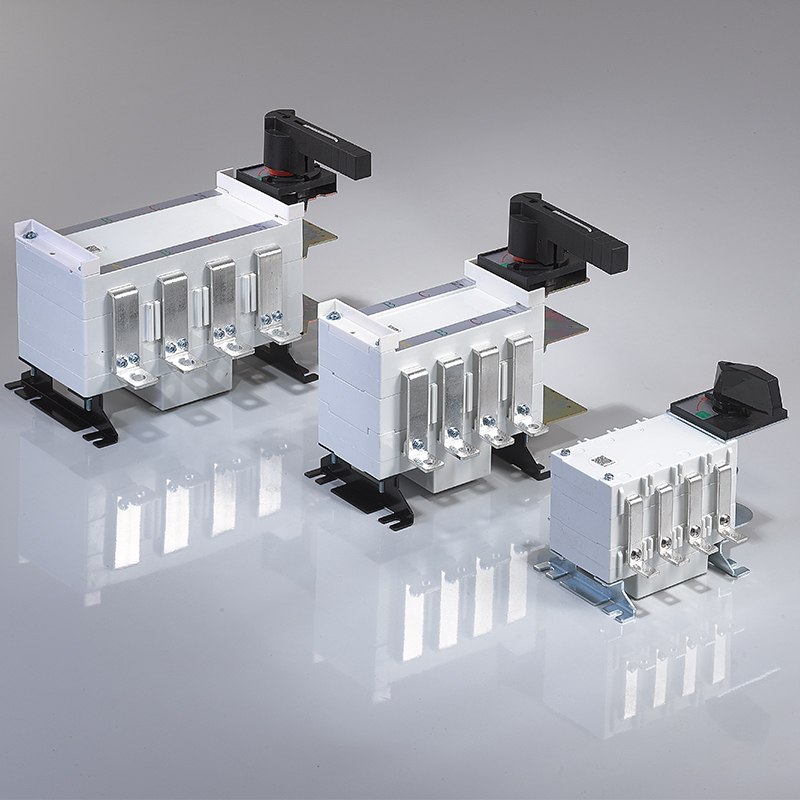
Selecting the correct switch architecture depends on available space, load demands, and panel integration requirements. For residential or light-commercial applications with limited space inside the main distribution board, the RDQ1 miniature manual transfer switch offers a highly efficient solution. Its DIN-rail mounting capability allows for rapid installation in tight enclosures. It provides excellent single-circuit isolation. Its compact form factor fits perfectly in scenarios requiring dedicated backup for specific, isolated equipment like a dedicated server rack or a standalone medical device. Installers frequently use these in secondary enclosures mounted directly adjacent to the main load center.
Standard modular applications require a balance of footprint and durability. The RMTS manual transfer switch excels in these environments. It integrates easily into existing secondary panels for multi-circuit management. The modular design allows installers to adapt the setup to varying load requirements without consuming excessive wall space. It provides heavy-duty mechanical switching for medium-demand residential and commercial sub-panels. This unit is particularly effective when retrofitting older electrical systems where space on the existing bus bar is completely exhausted.
Heavy-duty, high-amperage, or industrial isolation requires specialized hardware capable of handling massive fault currents. The RDGLZ manual changeover switch is engineered for these rigorous environments. It features heavy-duty mechanical interlock mechanisms that physically prevent simultaneous utility and generator connections. It is fully suitable for three-phase systems and commercial applications. Installers frequently deploy this switch in outdoor, meter-mounted 200A whole-panel configurations. Its heavy-duty contacts withstand high fault currents and frequent switching under heavy inductive loads without pitting or degrading.
Working inside a main electrical panel exposes you to lethal voltage and extreme arc flash hazards. Non-negotiable safety gear is required before removing the dead front cover. You must wear arc-flash rated leather protector gloves over rubber insulating gloves. Safety glasses with side shields protect against accidental sparks or flying metal debris. Use only insulated hand tools rated for 1,000 volts. Never substitute standard tools wrapped in electrical tape for true insulated variants when working near live bus bars.
Diagnostic equipment verifies safety and ensures proper functionality throughout the installation process. You need a digital multimeter with a Category III or Category IV rating to test voltage levels and continuity accurately. A non-contact voltage tester provides a rapid initial check for live current, though it should never replace a multimeter for final verification. A calibrated torque screwdriver is absolutely mandatory. Electrical terminals require precise tightening to manufacturer specifications, typically measured in inch-pounds. Under-torqued connections cause arcing, while over-torqued connections strip the threads and damage the wire.
Category III/IV Digital Multimeter
Non-Contact Voltage Tester
Calibrated Torque Screwdriver (10-50 in-lbs range)
1,000V Insulated Screwdriver Set
Wire Strippers and Heavy-Duty Cable Cutters
Fish Tape or Fiberglass Wire Pulling Rods
External hardware completes the physical installation. You need an outdoor power inlet box rated for either 30A or 50A, featuring a NEMA 3R weather-resistant rating. Select appropriately gauged feeder wire to connect the inlet box to the switch. Use 10 AWG THHN wire for 30-amp circuits. Use 6 AWG THHN wire for 50-amp circuits. Finally, acquire a heavy-duty, weather-resistant generator cord that matches your inlet box receptacle, typically an L14-30R or SS2-50R configuration.
Electrical installations must comply with standard NEC requirements. Article 702 governs Optional Standby Systems. It dictates exactly how transfer equipment must isolate power sources to prevent backfeeding. It also specifies requirements for load management, grounding, and mandatory signage. You must place permanent, engraved phenolic labels on the main panel indicating the presence of an alternative power source and the location of the outdoor disconnect.
Pulling local municipal permits is mandatory for this level of electrical work. Working inside the main service panel or installing a meter-mounted switch alters the building's core electrical infrastructure. Contact your local building department before beginning work to submit your wiring diagram and load calculations. You will likely need to schedule a utility disconnect. If your installation requires modifying the main service conductors or installing a switch between the meter and the main breaker, the utility company must pull the meter to de-energize the panel completely.
Begin by shutting off the main breaker at the top of the electrical panel. This cuts power to the branch circuit breakers. However, the incoming service lugs directly above the main breaker remain live and carry lethal, unfused current directly from the transformer. Utilize a non-contact voltage tester to verify a zero energy state across all branch bus bars and individual breakers. Follow up with your Category III multimeter. Set it to AC voltage and probe between the A phase, B phase, neutral, and ground to confirm zero volts.
Address the implementation risk of residual power and accidental re-energization. Implement Lockout/Tagout (LOTO) procedures if you are working in a commercial environment, a multi-tenant building, or any situation where the panel is out of your direct line of sight. Secure the main breaker in the off position using a breaker lockout device. Apply a physical padlock and a warning tag. This prevents anyone from accidentally restoring power while you have your hands inside the enclosure.
Select the mounting location for the indoor manual transfer switch carefully. It should be in close proximity to the main panel, ideally within 18 to 24 inches. This minimizes the length of the flexible conduit and wire runs, making the wire pulling process significantly easier. Ensure the enclosure sits at an ergonomic height for manual operation, typically matching the height of the main panel. Secure the box using appropriate anchors. Use heavy-duty drywall toggles for hollow walls. Use masonry anchors or Tapcons for concrete or cinder block installations. Ensure the enclosure is perfectly level before tightening the fasteners.
Mount the outdoor power inlet box on the exterior of the building. It must be a NEMA 3R rated enclosure to withstand rain, snow, and ice. Position it safely away from windows, doors, and HVAC intakes. A minimum clearance of 10 to 20 feet from any building opening is standard practice. This prevents lethal carbon monoxide ingress from the running generator. Secure the box to the siding or brick using exterior-grade screws. Seal the top and sides of the enclosure with exterior-grade silicone caulk to prevent water intrusion behind the box, leaving the bottom uncaulked to allow any condensation to weep out.
Install a flexible metallic conduit (FMC) or liquid-tight flexible non-metallic conduit (LFNC) between the main breaker panel and the indoor transfer switch. Remove the appropriate knockouts on both enclosures using a hammer and screwdriver, taking care not to damage the surrounding metal. Attach conduit connectors and secure them tightly with locknuts. The conduit protects the wires from physical damage and provides a continuous grounding path if you are using metallic conduit with proper bonding bushings.
Pull the pre-wired harness through the conduit. Feed the wires carefully to avoid scraping the insulation against the sharp edges of the knockouts. Keep the wires organized and untangled. If you are wiring a custom setup rather than a pre-wired harness, use a fish tape to pull the individual THHN conductors through the conduit. Apply a small amount of wire pulling lubricant if the conduit run has multiple bends or is particularly tight.
Route the heavy-gauge feeder cable from the outdoor power inlet box to the transfer switch. Drill a hole through the exterior wall using a masonry bit or hole saw, depending on your exterior material. Insert a PVC sleeve through the wall to protect the cable from abrasion against the rough edges of the structure. Feed the 10 AWG or 6 AWG cable through the wall. Seal the exterior penetration thoroughly with expanding foam or exterior-grade polyurethane sealant to maintain the building's thermal and moisture envelope.
Begin the main panel integration. Remove the panel cover and set it aside. Identify the existing breakers for your critical loads. Disconnect the hot wire from the first critical load breaker. Splice this existing wire to the corresponding load-side wire from the transfer switch. Use approved wire nuts or Wago 221 lever nuts, ensuring no bare copper is exposed outside the connector. Connect the corresponding utility-side wire from the transfer switch directly to the now-empty breaker terminal. Repeat this process systematically for each critical circuit, keeping the wire routing neat and following the perimeter of the panel.
Move to the switch panel termination. Strip the wire ends to the manufacturer's specified length, usually around half an inch. Insert each wire into its corresponding terminal in the transfer switch. Tighten every terminal screw using your torque screwdriver. Verify the torque setting matches the label inside the enclosure, which is often between 20 and 35 inch-pounds for branch circuits. Give each wire a firm tug after torquing to ensure it is seated securely under the terminal plate and not just pinched by the screw threads.
Execute your load management strategy based on your hardware. If you installed a 200A whole-panel switch, you manage loads by manually flipping breakers in your existing main panel. You must turn off non-essential breakers like electric ovens and air conditioners before switching to generator power. If you installed a 6-circuit or 10-circuit model, the dedicated breakers on the switch manage the loads. You simply flip the toggle switches from "Line" to "Gen" to transfer the power source for those specific circuits.
Labeling is a mandatory safety step. Clearly label every wire inside the panel using a label maker or permanent wire markers. Apply permanent labels to the front of the transfer switch. Match each toggle or breaker to its specific appliance or room. Accurate labeling ensures anyone in the household or facility can manage the electrical load safely during an outage without guessing which switch controls the well pump, furnace, or medical equipment.
Understand the strict distinction between grounding and bonding. Grounding connects the electrical system to the earth via a ground rod to dissipate lightning strikes or high-voltage surges. Bonding connects all non-current-carrying metal parts together to ensure fault current has a low-impedance path back to the source, which trips the breaker. Your transfer switch must integrate correctly with the main panel's grounding system to prevent electrocution hazards.
Connect the green ground wire from the transfer switch to the main panel's ground bus bar. Do not connect it to the neutral bus bar unless the main panel is the primary service equipment where neutral and ground are bonded together by the main bonding jumper. Ensure the ground wire from the outdoor power inlet box connects securely to the ground terminal in the transfer switch. This creates a continuous, safe return path for fault current back to the main service ground. If you are installing a separately derived system that switches the neutral, you must follow specific NEC grounding rules for the generator itself.
Do not restore utility power until you perform rigorous continuity checks. Use your multimeter set to the continuity or ohms function. Test for dead shorts between the hot phases, neutral, and ground. Place one probe on a hot terminal and the other on the ground bus. The meter should read infinite resistance (OL). A reading of zero ohms or a continuous beep indicates a dead short. Energizing a panel with a dead short will cause an immediate, violent arc flash and trip the main breaker.
Verify phase isolation and mechanical interlock functionality. The interlock must physically prevent the simultaneous connection of utility and generator inputs. Attempt to engage both sources at the same time manually. The interlock mechanism must block this action completely. Test continuity across the switch contacts to confirm that when the generator side is closed, the utility side is completely open, ensuring zero voltage can bleed back into the grid.
Turn off all branch breakers on the transfer switch and the main panel.
Safely connect the generator to the outdoor power inlet box using the heavy-duty generator cord. Align the prongs, insert the plug, and twist it clockwise to lock it into the receptacle.
Start the generator outdoors and let the engine warm up and stabilize for five minutes.
Switch the main transfer mechanism from utility to generator power.
Engage the critical circuits one by one. Start with the largest motor load, such as the refrigerator or well pump.
Monitor the generator's engine sound and check the voltage output. Wait for the engine to stabilize before engaging the next circuit to prevent voltage drops and stalling.
Under-torqued terminal screws are a frequent and dangerous error in field installations. Loose connections increase electrical resistance. This generates intense heat under load, leading to melted wire insulation, damaged breakers, and panel fires. Always use a calibrated torque screwdriver. Check every connection twice before replacing the dead front cover.
Improper neutral switching causes severe system instability and trips GFCI breakers. You must determine if your generator has a bonded neutral or a floating neutral. If the generator neutral is bonded to its frame, you typically need a 3-pole transfer switch that switches the neutral wire to comply with NEC requirements for separately derived systems. If the generator has a floating neutral, a standard 2-pole solid-neutral transfer switch is appropriate.
Avoid undersized power inlet boxes and exceeding generator capacity. Installing a 30A inlet box for a 12,000-watt generator restricts your power usage, overheats the wiring, and trips the inlet breaker constantly. Always match the inlet box and feeder wire ampacity to the maximum output of the generator. Never exceed the running wattage of the generator during the load test, as this degrades the alternator and damages sensitive electronics inside the building.
Establish a framework for bi-annual visual inspections. Open the panel covers and inspect the wiring for any signs of physical damage, moisture ingress, or pest intrusion. Look for loose connections or backed-out screws caused by thermal expansion and contraction. Perform mechanical exercising of the switch. Flip the transfer mechanism back and forth several times while the system is completely de-energized. This wiping action cleans the internal copper contacts, prevents oxidation buildup, and ensures smooth manual operation during an actual emergency.
Identify signs of wear that dictate immediate component replacement. Inspect the internal copper contacts for pitting, scarring, or carbon buildup caused by electrical arcing during load switching. Listen for unusual humming, buzzing, or chattering sounds when the switch is under load, which indicates poor contact pressure or failing springs. Look for thermal discoloration, brittle wire insulation, or melted plastic around the terminals. If you observe any of these indicators, replace the affected components or the entire switch assembly immediately to maintain system safety and prevent catastrophic failure.
Calculate your total continuous and peak surge wattage to finalize your hardware sizing requirements.
Select a 30A or 50A outdoor power inlet box that matches your generator's maximum output capacity.
Pull the required electrical permits from your local municipal building department before starting work.
Schedule a utility disconnect if your installation requires modifying the main service entrance conductors.
A: A 7500-watt generator produces roughly 31 amps at 240 volts. You need a 30-amp switch and a matching 30-amp power inlet box. A 30-amp setup safely handles up to 7,200 continuous watts, which perfectly aligns with the standard output profile of a 7500-watt portable generator.
A: Choose based on your generator's maximum output. Install a 30-amp box if your generator produces less than 7,500 running watts. Install a 50-amp box if your generator produces between 7,500 and 12,000 running watts. Ensure your feeder wire gauge strictly matches the box amperage.
A: Legality depends entirely on local municipal codes. Many jurisdictions allow homeowners to perform their own electrical work provided they pull the correct permits and pass a final inspection by a city official. However, working inside the main panel carries lethal risks. Professional installation is strongly recommended.
A: A changeover switch is a dedicated enclosure that routes power from specific circuits to either the utility or the generator. An interlock kit is a simple metal plate installed on your existing main panel. It physically prevents the main breaker and the generator breaker from being turned on simultaneously.
A: It depends on the switch design. A standard solid-neutral switch requires a floating neutral generator. If your generator has a bonded neutral, you must either unbond the generator (if permitted by the manufacturer) or install a switch that physically switches the neutral wire to comply with NEC rules.
A: Improper grounding eliminates the safe return path for fault current. If a short circuit occurs, the electrical current may energize the metal enclosure of the switch or the generator frame. This creates a severe electrocution hazard and prevents the circuit breakers from tripping during a fault.