
- All
- Product Name
- Product Keyword
- Product Model
- Product Summary
- Product Description
- Multi Field Search
Views: 0 Author: Site Editor Publish Time: 2026-08-14 Origin: Site


Industrial and commercial electrical systems demand absolute de-energization during maintenance. You achieve this through the precise installation of an isolator switch. Improper wiring introduces severe operational and safety risks. A single loose termination or crossed phase can trigger catastrophic arc flashes, phase-to-phase faults, or reverse motor rotation. Beyond physical danger, compliance violations immediately void facility insurance and halt operations. This guide provides a definitive, step-by-step technical framework for selecting, wiring, and verifying a three-phase isolation device. You will learn how to integrate these units with automated power transfer systems, interpret standard wiring diagrams, and execute mandatory testing protocols to ensure complete circuit safety before personnel begin maintenance work.
Terminal Precision: A standard 3-pole isolator switch requires exactly six primary connections (three supply, three load), plus dedicated routing for Earth and Neutral depending on the system architecture.
Safety First (LOTO): Mechanical lockout/tagout capabilities are mandatory; wiring must support verifiable physical disconnection and be performed by certified personnel.
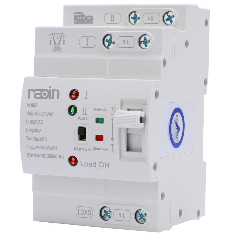
System Integration: Isolator switches are critical upstream components for safely maintaining complex backup systems, including any automatic transfer switch or PC class automatic transfer switch.
Verification is Mandatory: Visual inspection is insufficient; insulation resistance and continuity testing must validate the installation before re-energizing the circuit.
Before terminating any wires, installers must understand the internal mechanics of the switch. Failing to grasp this architecture leads to cross-phasing or the accidental bypassing of safety mechanisms. A three-phase switch physically breaks the circuit across all three live conductors simultaneously. This mechanical action isolates downstream equipment from the primary power source. The internal mechanism relies on a spring-loaded, quick-make and quick-break design. This ensures the contacts snap open or closed at a specific speed, regardless of how fast the operator moves the handle. This rapid action extinguishes electrical arcs before they can sustain themselves and damage the contact surfaces.
Standard terminal layouts follow a strict Line and Load designation. The incoming supply lines connect to the top terminals. Manufacturers universally mark these as L1, L2, and L3 in IEC regions, or sometimes A, B, and C in older NEMA panels. The outgoing load lines connect to the bottom terminals, designated as T1, T2, and T3. Inside the housing, a rigid mechanical linkage connects the three contact poles. When you throw the actuator handle, this linkage ensures the simultaneous opening or closing of all three phases. This synchronized action prevents single-phasing. Single-phasing destroys downstream three-phase motors by forcing them to draw excessive current on the remaining connected phases, leading to rapid thermal overload and stator winding failure.
Installers must differentiate between standard non-fused isolators and switch fuse units. A non-fused isolator, often called a switch disconnector, serves purely for isolation. It provides no overcurrent or short-circuit protection. You must rely on upstream circuit breakers or fuses for that protection. Conversely, a switch fuse unit incorporates localized overcurrent protection directly within the enclosure. These units contain high-rupturing-capacity (HRC) fuses that blow during a fault, offering an additional layer of localized equipment protection.
Feature | Non-Fused Isolator | Fused Isolator (Switch Fuse) |
|---|---|---|
Primary Function | Physical circuit isolation only. | Isolation plus overcurrent protection. |
Fault Interruption | Relies entirely on upstream breakers. | Internal HRC fuses clear local faults. |
Physical Size | Compact footprint, fits tight spaces. | Larger enclosure to house fuse carriers. |
Maintenance | Periodic contact inspection. | Requires replacement fuse inventory. |
Many industrial isolators feature auxiliary contacts. These low-voltage contacts operate in tandem with the main power poles. They come in normally open (NO) and normally closed (NC) configurations. Auxiliary contacts integrate directly with programmable logic controllers (PLCs) or motor control circuits. For example, wiring an NO contact to a variable frequency drive (VFD) ensures the drive disables its output the moment the isolator handle turns. This prevents the main contacts from breaking under a heavy inductive load, which extends the lifespan of the switch. You typically wire these control circuits using 14 AWG or 1.5mm² copper wire, completely separate from the main power conductors to prevent electromagnetic interference.
Matching the switch specifications to the operational load and facility requirements prevents premature failure. You must evaluate the electrical characteristics of the load before selecting the hardware. Undersizing the component leads to catastrophic failure during operation. You must calculate the continuous current draw and factor in the inrush current of any connected motors.
Switches carry specific utilization categories defined by IEC standards. Using the wrong category leads to severe arcing and contact welding.
Utilization Category | Typical Application | Switching Characteristics |
|---|---|---|
AC-21A | Resistive loads (heaters, lighting) | Switching of resistive loads including moderate overloads. |
AC-22A | Mixed resistive and inductive loads | Switching of mixed loads with moderate inductive components. |
AC-23A | Highly inductive motor loads | Frequent switching of highly inductive loads and heavy motors. |
Always select an AC-23A rated switch when controlling heavy machinery, compressors, or pumps. The AC-23A rating ensures the switch can safely interrupt the high locked-rotor currents associated with motor stalls or startups. If you install an AC-21A switch on a heavy motor circuit, the contacts will likely weld shut during the first emergency disconnect under load.
Consult the specific manufacturer schematic before beginning the installation. Wiring diagrams confirm terminal layouts and indicate whether the device supports bottom-feed configurations. While top-feed (supply on top) is standard, some panel designs require feeding from the bottom. The schematic will explicitly state if the switch is bi-directional. It also maps the routing for any auxiliary contact blocks attached to the side of the main housing. Never assume terminal layouts are identical across different brands. Always verify the internal bridging links if the schematic shows options for series or parallel pole configurations.
Regulatory standards mandate padlocking capabilities in the "OFF" position. This mechanical lockout/tagout (LOTO) feature ensures the switch cannot be accidentally re-energized while technicians work downstream. Installation requires strict adherence to safety protocols. Personnel must wear appropriate arc-flash personal protective equipment (PPE) as dictated by NFPA 70E or local equivalents. This includes voltage-rated gloves, safety glasses, and flame-resistant clothing. Before opening the panel, electricians must perform voltage verification using a calibrated multimeter to confirm a zero energy state. Test phase-to-phase and phase-to-ground. Only qualified, certified electricians may perform this installation.
Follow this sequential, evidence-based methodology to terminate connections safely and reliably. Skipping steps compromises the mechanical integrity and electrical safety of the installation.
Securely mount the enclosure or DIN rail component to the wall or panel backplate. The physical throw of a heavy-duty switch generates significant mechanical force. If the enclosure flexes or shifts during operation, it transfers mechanical stress directly to the terminal connections. Over time, this stress loosens the wire seating, increasing electrical resistance.
Mark the mounting holes using the enclosure as a template to ensure perfect alignment.
Drill pilot holes and insert heavy-duty wall anchors or tap threads for machine screws.
Secure the enclosure, ensuring it sits perfectly plumb and level to prevent internal binding.
Verify the actuator handle moves freely without scraping against the enclosure cover.
Maintain the enclosure's environmental rating by using appropriate IP-rated cable glands. For outdoor installations, specify IP65 or IP67 glands to prevent water ingress. Match the gland size (e.g., M20, M25, M32) to the outer diameter of your supply and load cables.
Drill or punch the knockout holes cleanly at the top and bottom of the enclosure.
Insert the cable glands and tighten the locknuts to seal against dust and moisture.
Route the incoming and outgoing cables through these glands, leaving enough slack for a drip loop.
If using steel wire armored (SWA) cable, terminate the armor correctly using designated brass earth tags and locking rings.
Strip the outer cable jacket, exposing the individual phase conductors.
Carefully strip the insulation from the copper conductors using calibrated wire strippers. Do not score or nick the underlying copper. Scoring reduces the cross-sectional area and creates a localized heating point.
If using stranded wire, crimp insulated bootlace ferrules onto the ends to prevent fraying and ensure maximum surface contact within the terminal lug.
Map the incoming supply phases to the top terminals (L1, L2, L3). Follow standard regional color codes. In IEC regions, this means Brown for L1, Black for L2, and Grey for L3. In North America, you will typically use Black, Red, and Blue. Insert the bare copper or ferruled ends fully into the terminal lugs. You must use a calibrated torque screwdriver. Tighten the terminal screws exactly to the manufacturer's specified torque rating, usually measured in Newton-meters (Nm) or inch-pounds (in-lbs). For example, a 100A switch might require exactly 35 in-lbs of torque. Under-tightening causes arcing. Over-tightening crushes the conductor and damages the terminal threads. Apply torque seal paint across the screw head and terminal block to provide a visual indicator that the connection is torqued and has not vibrated loose.
Map the outgoing cables to the bottom terminals (T1, T2, T3). Maintain strict phase sequence matching the supply side. L1 must connect through to T1, L2 to T2, and L3 to T3. Reversing any two phases causes downstream three-phase motors to rotate in reverse. This reverse rotation destroys pumps, compressors, and conveyor systems instantly upon startup. Secure these connections using the same torque specifications applied to the supply lines. Double-check that no stray copper strands protrude from the terminal blocks, as these can cause phase-to-phase flashovers.
Standard 3-pole isolators do not switch the neutral conductor. Route the neutral wire past the switch mechanism and terminate it at a solid, unswitched neutral link block inside the enclosure. If local electrical codes require neutral switching to isolate harmonic currents, you must install a 4-pole isolator switch instead. Terminate the protective earth (PE) conductor directly to the designated grounding busbar or earth terminal within the enclosure. Ensure continuous earth bonding between the supply cable armor, the metallic enclosure, and the load cable armor. Use a dedicated braided earth strap if the enclosure door houses any electrical components or metallic handles.
Manual isolation fits directly into automated power redundancy setups. These switches provide the physical disconnect points required to service complex transfer equipment safely without shutting down the entire facility.
You must place a manual isolator switch upstream of an automatic transfer switch. Transfer switches require periodic maintenance, contact cleaning, and mechanism testing. Without an upstream isolator, technicians cannot safely de-energize the ATS without dropping the entire facility's power at the main breaker. Installing isolators on both the primary utility feed and the secondary generator feed allows technicians to lock out power to the ATS enclosure. This facilitates safe, localized maintenance while the generator remains physically disconnected from the load.
Sub-panels often utilize a miniature auto transfer switch to manage localized critical loads, such as server racks, medical imaging equipment, or security systems. Wire an isolator switch directly ahead of these miniature units. This setup allows IT personnel or facility managers to isolate specific critical racks for UPS replacement or ATS servicing without disrupting adjacent circuits on the same distribution board. It provides granular control over the power infrastructure and prevents accidental tripping of main upstream breakers during localized maintenance.
When pairing an isolator with a PC class automatic transfer switch, specific short-circuit making and withstanding requirements apply. A PC class ATS does not include integral short-circuit protection. It relies entirely on robust upstream protection and isolation. The upstream isolator must possess a short-circuit withstand rating (Icw) that exceeds the maximum prospective fault current of the system. This ensures the isolator contacts will not blow open or weld shut during a severe downstream fault before the main circuit breaker trips. Coordinate the isolator's withstand rating with the clearing time of the upstream protective device.
Identifying and preventing standard installation errors protects both the equipment and the personnel operating it. Most failures originate from poor termination practices rather than hardware defects.
Loose connections remain the most frequent cause of switch failure. A loose terminal increases electrical resistance at the connection point. As current flows through this high-resistance joint, it generates heat. This localized heating causes the copper conductor and brass terminal to expand and contract, loosening the connection further. This cycle accelerates into thermal runaway, leading to terminal degradation, melted insulation, and eventual electrical panel fires. Always use a torque wrench and mark tightened screws with torque seal paint to provide visual confirmation of proper seating. Never rely on hand-tight estimates.
Crossing L2 and L3 during termination alters the phase rotation. As previously noted, this causes HVAC compressors, industrial fans, and hydraulic pumps to run backward. Mechanical damage occurs within seconds. To prevent this, electricians must use a phase rotation meter on the supply lines before termination. They must verify the rotation again at the load terminals before coupling any motors to their driven equipment. Document the phase rotation sequence on the panel schedule for future reference.
Wiring a single-phase load through a 3-phase isolator switch is technically possible but requires careful configuration. You can wire the live conductor through one pole and leave the other two unused. Alternatively, you can wire the poles in series to increase the DC breaking capacity. However, you must evaluate compliance and rating implications. Some local electrical codes prohibit using multi-phase equipment for single-phase loads unless explicitly approved by the manufacturer. Furthermore, unused poles can accumulate dust and moisture, potentially compromising the internal tracking resistance over time.
Visual inspection is insufficient. You must prove the installation is safe and functional through rigorous testing before commissioning the circuit. Document all test results for compliance records.
Use a Megger (insulation resistance tester) to verify the integrity of the installation. Apply a 500V or 1000V DC test voltage between phases, and between each phase and earth. This verifies no phase-to-phase or phase-to-earth shorts exist due to pinched wires or damaged insulation. Acceptable resistance values typically exceed 1 Megohm, though higher voltage systems require higher minimums. After testing, discharge the cables to ground to remove any residual capacitive charge. Next, test continuity across the poles in the closed position. A micro-ohmmeter should show near-zero, perfectly balanced resistance across L1-T1, L2-T2, and L3-T3. Uneven resistance indicates a poorly seated wire or a defective internal contact.
Verify the mechanical throw of the handle. It should snap cleanly and decisively into the ON and OFF positions without binding or grinding. The lockout mechanism must accept a standard padlock smoothly. Once mechanical checks pass, proceed with a controlled initial energization. Monitor the switch under load. After 30 minutes of operation at normal capacity, use a thermal imaging camera to scan the enclosure and terminals. Set the camera's emissivity correctly for the terminal materials (typically around 0.95 for oxidized copper or standard cable insulation). Look for localized hot spots. A temperature difference (Delta-T) of more than 10°C between phases indicates a high-resistance connection requiring immediate re-torquing.
Procure a calibrated torque screwdriver and verify all terminal connections meet the manufacturer's exact inch-pound or Newton-meter specifications.
Test the phase rotation on both the line and load sides using a digital phase rotation meter before coupling any driven equipment.
Perform a 1000V DC insulation resistance test across all poles and to ground, documenting the Megohm readings for compliance records.
Install standardized lockout/tagout (LOTO) padlocks on the actuator handle and train facility personnel on the isolation procedure.
A: A standard 3-pole isolator switch features exactly six primary connections. It has three incoming supply terminals (L1, L2, L3) and three outgoing load terminals (T1, T2, T3). Depending on the system architecture, you will also need separate provisions for routing the Earth and Neutral conductors through the enclosure.
A: Yes, it is technically possible. You can route the single live wire through one pole, or loop it through multiple poles in series to improve breaking capacity. However, you must check local electrical codes and manufacturer guidelines to ensure compliance before implementing this configuration.
A: You should install the isolator switch directly upstream of the automatic transfer switch. Placing isolators on both the primary utility feed and the backup generator feed allows technicians to safely isolate and de-energize the transfer mechanism for routine maintenance and repairs.
A: A standard 3-pole switch does not switch the neutral conductor. The neutral simply passes through the enclosure via a solid, unswitched terminal link. If your local electrical regulations require the neutral to be physically disconnected during isolation, you must install a 4-pole isolator switch instead.
A: An isolator switch is an off-load device designed purely to provide a physical, verifiable disconnection point for safe maintenance. It does not automatically trip during faults. A circuit breaker is an on-load protective device designed to automatically interrupt power during overcurrent or short-circuit events.