
- All
- Product Name
- Product Keyword
- Product Model
- Product Summary
- Product Description
- Multi Field Search
Views: 0 Author: Site Editor Publish Time: 2026-08-09 Origin: Site


Confusing an off-load mechanical disconnect with an active fault protection device introduces severe safety risks. High-voltage industrial environments demand precise equipment application. Misapplying these components causes catastrophic equipment failure. It triggers severe arc flash incidents. Unplanned downtime disrupts critical operations. Strict safety compliance violations follow, particularly concerning OSHA and NFPA 70E standards. International standards, such as IEC, often refer to an isolator switch as a "disconnector." This specific terminology distinguishes it from general-purpose load-break switches. Both devices interrupt electrical continuity. However, their operational behavior, physical placement, and engineering purposes remain fundamentally different. This article provides a technical evaluation framework. You will learn how to specify the correct device. We base this selection guide on load conditions, protection requirements, and system architecture.
Operational State: A circuit breaker is designed to operate under load (on-load) to actively protect against faults, whereas an isolator switch must only be operated when the current is already zero (off-load).
Protection vs. Isolation: Circuit breakers provide automatic overcurrent and short-circuit protection; isolator switches provide a visible, manual break in the circuit for safe maintenance.
Arc Extinguishing: Circuit breakers contain internal arc chutes or vacuum chambers to extinguish electrical arcs during switching; isolator switches lack this capability, making under-load operation highly dangerous.
System Synergy: Industrial power systems require both devices working in sequence—breakers for active protection and isolators for verifiable maintenance isolation.
An isolator switch functions as a mechanical switching device. It provides a highly visible isolating distance when set to the open position. Engineers deploy this device to ensure complete circuit de-energization. This state allows safe human intervention during maintenance. Lockout/Tagout (LOTO) procedures rely heavily on this physical break. When you stand in front of a medium-voltage switchgear lineup, you need absolute certainty the power is off. The isolator gives you that visual confirmation. The device lacks any automatic tripping mechanisms. It cannot detect overloads or short circuits. You must operate it strictly under off-load conditions. Opening the contacts while current flows creates extreme hazards. The design focuses entirely on isolation rather than active protection. It serves as a passive safety barrier for maintenance personnel. We install these specifically to meet strict OSHA isolation requirements.
A circuit breaker acts as a complex electromechanical device. It safely makes, carries, and breaks electrical currents. It performs these functions under both normal and abnormal conditions. Abnormal conditions include severe overloads and short-circuit faults. The internal architecture includes sensitive relays and trip units. These units utilize thermal-magnetic or electronic detection methods. They constantly monitor current flow and detect anomalies instantly. Upon detecting a fault, the mechanism automatically trips. This action interrupts the current flow to protect downstream equipment. The breaker actively manages the electrical load and mitigates fault damage. It serves as the primary line of defense in an electrical network. When a heavy industrial motor shorts out, the breaker clears the fault before the feeder cables melt. You rely on it for dynamic, real-time system protection.
Circuit breakers interrupt active current flow safely. They operate seamlessly under full load conditions. They also break massive fault currents without sustaining damage. You can manually open a breaker while the facility draws peak power. Isolators require a pre-de-energized state. You must stop the current flow before operating the isolator. Breaking a live circuit with an isolator causes sustained arcing. The air between the separating contacts ionizes rapidly. This ionization creates a conductive plasma channel. The plasma sustains the electrical arc until the contacts melt or vaporize. This physical limitation strictly defines the isolator's off-load requirement. Field technicians learn early on never to pull an isolator handle if the panel ammeter shows current.
Breakers function as active, intelligent protection devices. They monitor the circuit continuously using current transformers and potential transformers. When current exceeds safe thresholds, they react automatically. They clear short circuits in milliseconds. Modern electronic trip units allow you to adjust long-time, short-time, instantaneous, and ground fault settings. An isolator switch remains a completely passive component. It offers zero protection against electrical faults. It will not open automatically during an overload. It will simply conduct the fault current until upstream protection operates. If upstream protection fails, the isolator will eventually suffer thermal destruction. It has no sensors and no trip coil.
Circuit breakers feature sophisticated internal architectures to manage electrical arcs. Low-voltage breakers utilize arc chutes. These chutes contain stacked metal plates. Magnetic forces drive the arc into these plates. The plates divide, stretch, and cool the arc until it extinguishes. Medium and high-voltage breakers use vacuum interrupters or SF6 gas. Vacuum chambers remove the air, preventing ionization entirely. SF6 gas absorbs free electrons rapidly to quench the arc. Isolators feature simple contact separation in open air. They lack arc chutes, vacuum chambers, or quenching gases. This absence of arc mitigation makes under-load operation physically impossible and highly dangerous. When you open an isolator, you rely entirely on the physical distance between the copper blades to prevent flashover.
Single-line diagrams dictate specific placement rules. Engineers position isolators strategically around circuit breakers. You typically find an isolator upstream before the breaker. You often find another isolator downstream after the breaker. This configuration isolates the breaker itself. Technicians can safely remove the breaker for testing or replacement. The breaker sits in the main current path to protect the load. The isolators bracket the breaker to provide maintenance boundaries. In a typical substation layout, the incoming line hits an isolator first, then the main breaker, then the busbar. This allows complete de-energization of the breaker for annual maintenance without relying on utility-side switches.
Circuit breakers operate automatically during fault conditions. The internal trip unit forces the contacts open without human input. Operators can also open or close them manually using spring-charged mechanisms. Facilities often control breakers remotely via SCADA systems using motorized operators and shunt trips. Isolators operate predominantly through manual actuation. Technicians use physical handles, rotary drives, or insulated operating poles to move the contacts. Motorized isolators do exist for specific high-voltage grid applications. However, even motorized versions lack automatic fault-response capabilities. They only move when commanded by an operator or control system. You will never see an isolator open on its own to clear a fault.
Isolators provide a guaranteed, visible physical break in the circuit. You can look at the device and see the air gap between the contacts. This visible break forms a strict requirement for maintenance safety protocols. Workers trust their eyes before touching high-voltage conductors. Circuit breakers often enclose their contacts deeply within molded cases or metal-clad switchgear. You cannot see the actual contacts separating. Breakers rely on mechanical indicator flags to show their status. Indicators can mechanically fail. A broken linkage might show an open status while the contacts remain welded shut. This mechanical uncertainty is exactly why you never rely on a breaker alone for LOTO.
High-voltage power lines retain dangerous capacitive charges even after disconnection. Long cable runs act like giant capacitors. Isolators frequently feature integrated earth switches. These switches safely discharge residual current to the ground grid. Operators close the earth switch only after opening the main isolator contacts. Mechanical interlocks prevent closing the earth switch while the main contacts remain closed. Circuit breakers typically do not include integrated earth switches. Their primary job is current interruption, not residual charge management. When we isolate a 33kV feeder, we open the breaker, open the isolator, and then throw the earth switch to bleed off the trapped charge before applying working grounds.
Circuit breakers demand high financial investment. Their internal electromechanical components are highly complex. They require precision-engineered trip units, arc chutes, and heavy-duty operating mechanisms. Regular maintenance and testing add to their lifecycle cost. You have to test the trip curves and contact timing regularly. Isolators offer a simpler, highly robust mechanical design. They consist primarily of copper contacts, insulators, and a manual linkage. This simplicity makes them highly cost-effective. They require minimal maintenance compared to active breakers. The structural focus remains on mechanical endurance rather than electrical interruption. You grease the pivot points, check the contact alignment, and measure the resistance.
Evaluation Dimension | Isolator Switch | Circuit Breaker |
|---|---|---|
Primary Function | Visible mechanical isolation for maintenance | Active fault protection and load switching |
Operational State | Strictly Off-Load | On-Load and Fault Conditions |
Arc Extinguishing | None | Arc chutes, vacuum bottles, or SF6 gas |
Actuation Method | Manual (predominantly) | Automatic (on fault), Manual, Remote |
Safety Verification | Visible contact separation | Mechanical indicator flags |
Cost & Complexity | Low cost, simple mechanics | High cost, complex electromechanics |
Industrial safety relies on strict sequential operation protocols. Operators must memorize and execute these steps flawlessly to prevent catastrophic equipment damage. We often post these switching orders directly on the switchgear doors:
Open the circuit breaker first to safely interrupt the active load and drop current flow to zero.
Open the isolator switch to achieve verifiable mechanical isolation.
Apply LOTO devices to the isolator's physical locking points.
To restore power, remove LOTO devices and close the isolator switch first while the circuit remains dead.
Close the circuit breaker last to restore power to the load.
Power source redundancy requires an automatic transfer switch. This device manages transitions between utility power and backup generators. System designers place isolator switches strategically around the ATS. This placement allows for complete bypass operations. Technicians can isolate the ATS for maintenance without dropping the critical load. The isolator provides the necessary physical break. The transfer switch handles the active load management. This combination ensures continuous power availability and safe maintenance access. Facilities cannot perform intrusive ATS maintenance safely without dedicated isolation points. You use bypass-isolation configurations in hospitals and data centers to keep the lights on during service.
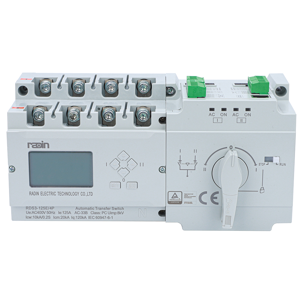
A PC class automatic transfer switch features a mechanically held design. It easily makes and withstands high short-circuit currents. However, it is not intended to break short-circuit currents. This characteristic makes it mechanically robust. It shares similarities with standard isolators regarding mechanical endurance. Yet, it actively transfers loads between different power sources. Standard isolators only disconnect a single line. CB class transfer switches include built-in overcurrent protection. PC class devices rely on upstream breakers for fault clearing. This distinction dictates specific system integration strategies. Engineers must coordinate the PC class ATS with external protection devices to ensure the system survives a fault.
Modern facilities often utilize a remote transfer switch for distributed power control. This equipment interfaces directly with upstream circuit breakers. The breakers provide necessary fault protection. The remote switch manages the load transfer sequence based on external controller inputs. Local isolator switches remain critical in this architecture. They provide physical maintenance safety near the remote equipment. Technicians rely on these local disconnects for localized LOTO procedures. The remote switch handles operational transitions. The isolator guarantees human safety during physical inspections. Both components work together to balance automation with manual safety protocols. You never want to work on a remote-controlled device without a local, padlocked disconnect open.
Selecting equipment requires matching specific electrical ratings. You must evaluate the short-circuit withstand current of the isolator. This rating indicates how much fault current the device can survive mechanically and thermally for a specific duration. The isolator must withstand this stress until the upstream breaker clears the fault. You pair this with the breaking capacity of the circuit breaker. The breaker must interrupt the maximum available fault current at that specific network node. Voltage ratings must also align. A 12kV system requires both devices to possess adequate dielectric strength for 12kV operations. Mismatched ratings lead to catastrophic failures during short-circuit events. The magnetic forces during a fault can physically rip an underrated isolator off its mounts.
Industrial components must adhere to strict international standards. Circuit breakers generally fall under IEC 60947-2. This standard dictates rigorous testing for fault interruption and trip unit accuracy. Isolators and disconnectors fall under IEC 60947-3. This standard focuses on mechanical endurance, isolation distances, and off-load switching capabilities. In North America, UL 98 covers enclosed and dead-front switches. OSHA regulations mandate strict LOTO compliance. Your selected isolator must accommodate physical padlocks. It must provide an unambiguous visual indication of contact separation to meet these regulatory demands. Inspectors will fail a facility if the isolation points do not meet these visible break requirements.
Operating environments heavily influence equipment selection. Dust, moisture, and corrosive gases degrade electrical contacts rapidly. You must specify the correct enclosure type for both devices. Indoor climate-controlled substations allow for standard NEMA 1 or IP20 enclosures. Outdoor installations require NEMA 3R or IP54 ratings to withstand rain and ice. Explosive atmospheres demand specialized hazardous location enclosures. Isolators in harsh environments often utilize sealed gas compartments. Breakers may require internal heaters to prevent condensation on trip units. Evaluate the ambient temperature range, altitude, and pollution degree before finalizing specifications. A breaker rated for sea level will overheat at high altitudes due to thinner air.
Operating an isolator under load constitutes a critical safety violation. The consequences are immediate and severe. As the contacts separate, the current continues to flow through the air. This creates a massive electrical arc. The temperature of the arc flash can exceed 35,000 degrees Fahrenheit. This intense heat vaporizes the copper contacts instantly. The rapid expansion of vaporized metal creates an explosive pressure wave. Equipment destruction is guaranteed. Operator injury or fatality is highly probable. The lack of arc extinguishing mechanisms makes this action entirely indefensible in any industrial setting. We treat every closed isolator as a loaded hazard until we verify the upstream breaker is open.
Engineers mitigate human error through robust interlocking systems. Mechanical interlocks physically prevent incorrect operation sequences. Castell keys represent a common solution. A technician cannot remove the key from the circuit breaker until the breaker is locked in the open position. The technician then uses this same key to unlock the isolator switch. This physical transfer ensures the isolator cannot move while the breaker remains closed. Electrical interlocks use auxiliary contacts to achieve similar results. They cut control power to motorized isolators if the main breaker detects current flow. These systems enforce the correct sequential operation protocols automatically. You design the system so the operator physically cannot make a mistake.
Both devices require distinct maintenance approaches. Circuit breakers demand rigorous testing of their active components. Technicians must perform primary or secondary injection testing on the trip units. This verifies the breaker will operate accurately during a fault. Contact timing tests ensure all three phases open simultaneously. Isolators require different testing realities. Maintenance focuses on contact resistance measurements. High resistance indicates worn or oxidized contacts. Technicians also inspect the mechanical linkages for wear and lubricate pivot points. Regular thermal imaging under load helps identify failing connections in both devices before catastrophic failure occurs. A hot spot on an isolator jaw usually means the spring tension is failing.
Take the following immediate actions to ensure electrical system integrity and personnel safety:
Consult with a licensed electrical engineer to review and update your facility's single-line diagrams.
Conduct a comprehensive arc flash hazard analysis to verify current equipment ratings against available fault currents.
Implement strict mechanical interlocking systems between all paired breakers and isolators to prevent out-of-sequence operations.
Audit your existing Lockout/Tagout procedures to ensure they mandate visual break verification before maintenance begins.
A: No. Isolator switches completely lack arc extinguishing mechanisms like arc chutes or vacuum chambers. Opening them under load creates a sustained, high-temperature electrical arc. This causes severe arc flash explosions, vaporizes the contacts, destroys the equipment, and poses a fatal risk to the operator.
A: Yes. They perform entirely different functions. The circuit breaker provides active, automatic protection against overloads and short circuits. The isolator switch provides a passive, highly visible mechanical break in the circuit. You need the isolator to guarantee human safety during maintenance procedures.
A: In IEC standards, "isolator" and "disconnector" are used interchangeably to describe devices strictly meant for off-load operation. "Disconnect switch" is a broader term used primarily in North America. Depending on the specific design and regional terminology, a disconnect switch might be rated to break load currents.
A: A PC class ATS actively transfers electrical loads between two different power sources and can withstand high short-circuit currents. A standard isolator simply disconnects a single power line to create a safe working boundary for maintenance.
A: Sometimes. Specific devices known as "isolating circuit breakers" meet the stringent standards for both functions. However, they must possess a verifiable visible break or a highly reliable, mechanically linked position indication system that strictly complies with isolation standards.
A: It is a matter of engineering purpose and cost efficiency. Isolators are designed exclusively for off-load operation to provide maintenance safety. Adding complex arc chutes or vacuum chambers would unnecessarily increase their size, complexity, and cost, duplicating the function already handled by the circuit breaker.