
- All
- Product Name
- Product Keyword
- Product Model
- Product Summary
- Product Description
- Multi Field Search
Views: 0 Author: Site Editor Publish Time: 2026-08-25 Origin: Site


Transient overvoltages present severe operational risks to modern electrical infrastructure. A single lightning strike or internal grid fluctuation can destroy sensitive electronics instantly, halting production lines and damaging data centers. Even premium hardware fails when installed improperly. Incorrect wiring, excessive lead lengths, and mismatched specifications cause catastrophic equipment failure. These installation errors also void manufacturer warranties, leaving facilities completely exposed to electrical anomalies. Facility managers and electrical contractors must address common failure points in electrical protection directly at the panel level. A rigorous, standards-compliant framework is necessary for evaluating, preparing, and executing the setup. Proper installation ensures maximum discharge capacity and guarantees regulatory compliance. This guide provides actionable technical steps to secure your electrical panels against destructive transient events, focusing on practical field execution and strict code adherence.
Location Dictates Efficacy: Minimizing conductor lead length (ideally under 18 inches) is the single most critical factor in reducing let-through voltage during a surge event.
Specification Matching is Non-Negotiable: Verifying system voltage, phase configuration, and required discharge capacity (e.g., selecting a 100kA rating for high-exposure panels) must precede any physical installation.
Strict Adherence to Safety Standards: All installations require complete power isolation, verified by multimeter testing, and must comply with local electrical codes (e.g., NEC Article 285).
Tiered Protection Strategy: Effective facility protection relies on coordinating primary service entrance devices with downstream units like a T2 class surge arrester at distribution boards.
A successful installation hinges on clamping voltage performance, hardware longevity, and strict code compliance. You cannot achieve these metrics without verifying the electrical environment before mounting any hardware. Rushing the specification phase leads to inadequate protection or immediate device failure upon energization. Field technicians must gather empirical data from the panel rather than relying on outdated single-line diagrams.
You must measure the exact voltage characteristics of the target panel. Use a calibrated true-RMS multimeter to capture accurate readings. Measure phase-to-phase, phase-to-neutral, and phase-to-ground voltages. Document these readings carefully. Electrical systems vary wildly, and assuming nominal voltage based on faded panel labels is a dangerous practice that often results in blown modules.
Differentiate between single-phase, split-phase, and three-phase configurations. A 120/240V residential split-phase system requires a completely different internal topology than a 277/480V three-phase Wye commercial system. Installing a unit with an incorrect Maximum Continuous Operating Voltage (MCOV) is a fatal error. If the MCOV is too low, normal grid voltage fluctuations will force the internal metal oxide varistors (MOVs) into continuous conduction. This leads directly to thermal runaway, melting the enclosure, and potentially causing a panel fire.
Nominal System Voltage | Phase Configuration | Minimum Recommended MCOV | Typical Application |
|---|---|---|---|
120/240V | Single-Phase / Split-Phase | 150V (L-N) | Residential load centers, light commercial panels. |
120/208V | Three-Phase Wye | 150V (L-N) | Commercial office buildings, retail distribution boards. |
277/480V | Three-Phase Wye | 320V (L-N) | Industrial manufacturing facilities, heavy machinery. |
480V | Three-Phase Delta (Ungrounded) | 550V (L-L) | Legacy industrial plants, specific motor control centers. |
Discharge capacity dictates how much transient energy the unit can safely divert to ground without sustaining damage. You must base this selection on geographic lightning density and facility exposure. Facilities located in high-lightning regions or at the end of long rural distribution lines face massive exposure to external transients.
For robust industrial or commercial panel defense, specifying a 100kA surge protector ensures the unit can withstand multiple high-energy strikes over its lifespan. While a single lightning strike rarely delivers more than 20kA to 30kA to a specific panel, the 100kA rating provides a massive thermal buffer. Standard residential load centers might only require 36kA to 50kA ratings. However, specifying higher capacities at the main service entrance extends the operational life of the unit by distributing the thermal stress across larger internal components.
Understanding the application category prevents code violations and functional limitations. Type 1 and Type 2 designations dictate where you can legally install the hardware and whether you need additional overcurrent protection.
A T2 class surge arrester plays a specific role in a tiered protection strategy. While Type 1 units absorb the massive external hits at the service entrance, Type 2 units clean up the residual energy that slips past. They also neutralize internally generated transients caused by large motors, HVAC compressors, and heavy machinery cycling on and off within the facility. You must install Type 2 devices on the load side of the main disconnect, and they require a dedicated breaker to isolate them from the busbar in the event of a catastrophic internal short.
Working inside live electrical panels presents lethal arc flash and shock hazards. You must establish a rigid safety protocol before opening any enclosures. Regulatory bodies provide strict guidelines for hard-wired installations, and bypassing these rules puts both the installer and the facility at risk.
All hard-wired installations must comply with the National Electrical Code (NEC) Article 285. This article governs the placement, conductor sizing, and connection methods for transient voltage surge suppressors. Furthermore, the hardware itself must carry a UL 1449 4th Edition certification, ensuring it has passed rigorous fault current and thermal runaway testing. OSHA regulations dictate the safety procedures you must follow during the physical integration process, specifically regarding energy isolation.
Do not attempt this installation with standard hand tools. You need specialized equipment to ensure safety and precision. Gather the following items before beginning the task:
Arc Flash Personal Protective Equipment (PPE) rated for the panel's specific fault current, including a face shield and balaclava.
Insulated voltage-rated gloves with leather protectors, inspected for pinholes prior to use.
A calibrated true-RMS multimeter with CAT III or CAT IV rated probes.
Insulated torque screwdrivers and wrenches to meet manufacturer torque specifications.
Hydraulic knockout punches for creating clean conduit entries without generating metal shavings.
A dedicated lockout/tagout (LOTO) kit with non-conductive padlocks and highly visible tags.
Conduct a thorough visual inspection of the panelboard. Identify the available fault current ratings printed on the main breaker. Check the physical condition of the busbars and neutral lugs. Ensure you have adequate working clearances as mandated by NEC Article 110.26. If the panel shows signs of severe corrosion, moisture ingress, or thermal damage, you must halt the installation and address those structural issues first. Installing new protection hardware on a compromised busbar guarantees future failure.
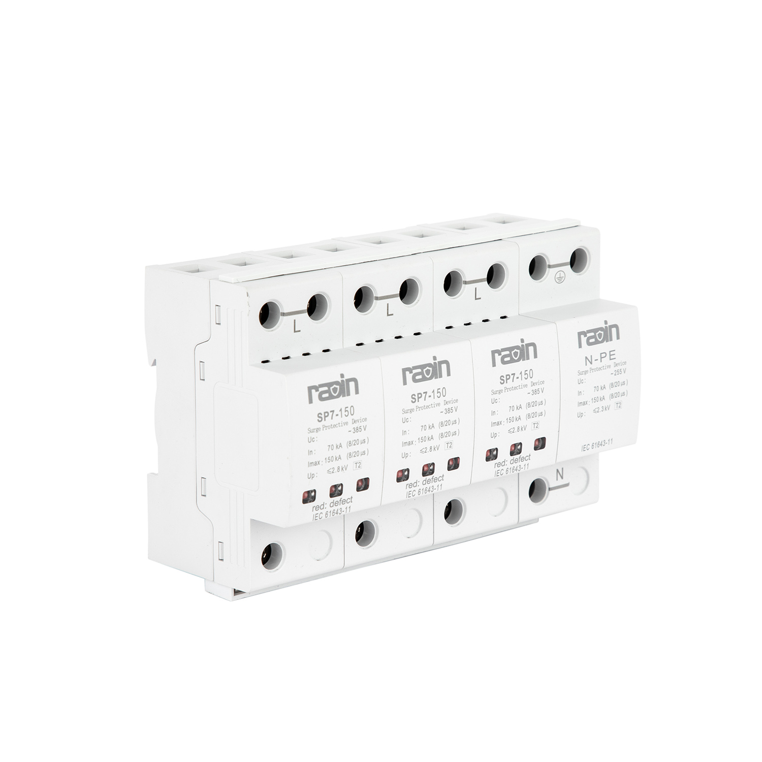
Execution requires precision. The physics of high-frequency transients mean that sloppy wiring directly degrades the protection level. Follow this sequence strictly to achieve optimal clamping performance and maintain a low-impedance path to ground.
Never install hard-wired protection on an energized panel. Apply your Lockout/Tagout (LOTO) devices to the main service disconnect. Secure the lock and keep the key on your person. Warn all facility personnel that power will remain off for the duration of the task.
Verify zero energy using your true-RMS multimeter. First, test the meter on a known live source to confirm it functions correctly. Then, test phase-to-phase across all incoming lines in the target panel. Test each phase to neutral. Finally, test each phase to ground. You must see zero volts on all measurements. Do not rely on non-contact voltage testers for this verification, as they can produce false negatives in shielded environments or near grounded metal enclosures.
High-frequency surge events behave differently than standard 60Hz alternating current. During a transient strike, wire impedance becomes the dominant factor. Every inch of conductor wire adds roughly 15 to 25 volts of let-through voltage to the protected equipment due to the rapid rate of current rise (di/dt). Therefore, locating the surge protection device as close to the breaker panel as physically possible is mandatory.
Identify a mounting location that allows for the shortest, straightest wire path. Ideally, position the unit directly adjacent to the dedicated breaker. If protecting a specific control cabinet, install the device at the exact point of cable entry. This prevents transient interference from coupling into sensitive internal wiring via electromagnetic induction. If you mount the unit three feet away from the panel, the added wire inductance renders the protection virtually useless for sensitive electronics.
Once you select the optimal location, prepare the enclosures. Use a hydraulic knockout punch to create a hole in the host panel and the protection unit's housing. Align these knockouts perfectly to minimize the distance between them. Avoid using standard twist drill bits or hole saws if possible, as metal shavings can fall onto live busbars and cause catastrophic arc faults upon energization.
Use a short metal nipple or a piece of flexible conduit to connect the two enclosures. Secure the conduit with appropriate locknuts and grounding bushings. The physical mounting must be rigid to withstand vibration and maintain grounding continuity if you are using metallic conduit as an equipment ground. Ensure the enclosure is mounted at a height that allows technicians to easily read the diagnostic LEDs during routine walk-throughs.
Route the conductors through the conduit. Keep the wires as short as possible. Cut off any excess length; never coil spare wire inside the panel. Coiled wire acts as an inductor, creating massive impedance that blocks high-frequency surge energy from reaching the ground, forcing it instead into your facility's equipment.
Follow a strict termination sequence. Connect the ground wire first. Secure it to the main grounding busbar. Next, connect the neutral wire (typically white) to the neutral bar. Finally, connect the phase conductors (typically black or red) to the designated breaker. Type 2 installations usually require a dedicated 20A or 30A maximum breaker. Check the manufacturer's specification sheet for the exact breaker sizing.
When routing the wires, avoid sharp 90-degree bends. High-frequency energy struggles to navigate sharp corners, which increases localized impedance. Keep all wire radiuses broad and sweeping. You can twist the phase, neutral, and ground wires together loosely; this technique helps cancel out electromagnetic fields and slightly reduces overall inductance. Never splice the wires; a continuous, unbroken copper path is essential.
Modern industrial systems often utilize modular architectures for easier maintenance. We can use the SP5-C series T2 class surge protector as an evaluation model for this step. These modular units feature a fixed base and replaceable protection cartridges, allowing technicians to swap out degraded MOVs without disconnecting the base wiring.
Mount the DIN rail base securely inside the control cabinet or distribution board. Terminate your wiring to the base terminals following the short-path rules and torque the lugs to the exact inch-pound specification listed on the device. Once wired, firmly seat the replaceable cartridges into the base. You should feel a positive click confirming they are locked in place. Next, wire the remote signaling contacts (dry contacts). Connect these small-gauge wires to your facility's monitoring system to receive instant alerts if a cartridge sacrifices itself during a strike.
Even with careful planning, specific installation variables can severely compromise system efficacy. You must actively mitigate these risks during the physical setup to ensure the hardware performs to its rated specifications.
We cannot overstate the impact of lead length. If you use three feet of wire to connect the unit to the breaker, you add massive impedance. A 10kA surge with a high rate of rise pushing through 36 inches of wire can add hundreds of volts to the clamping voltage. This excess voltage hits your sensitive servers, PLCs, and motor drives. Keep leads under 18 inches. If you cannot achieve this, you must relocate the unit, use a direct busbar connection if the panel design allows, or utilize a Kelvin connection (V-wiring) to eliminate the lead length penalty entirely.
Protection hardware does not absorb surge energy; it diverts it to the earth. Therefore, the device is only as effective as the facility's grounding system. If your ground resistance is too high, the surge energy will seek alternative paths through your networked equipment, destroying communication ports and power supplies.
Measure the facility's ground resistance using a 3-pole fall-of-potential tester. Operational thresholds typically require ground resistance to be under 25 ohms, though sensitive data centers often demand under 5 ohms. If the grounding system is inadequate, you must drive additional ground rods, install a ground ring, or chemically treat the soil before relying on the protection hardware.
Using shared breakers introduces significant risk. If a shared load trips the breaker, your protection is offline without any localized warning. Always use a dedicated Overcurrent Protection Device (OCPD). Properly size this breaker to prevent nuisance tripping during minor voltage fluctuations, but ensure it does not exceed the manufacturer's maximum rating. Overtightening the breaker lugs can sever wire strands, increasing resistance and creating a hot spot. Always use an insulated torque screwdriver to meet the exact inch-pound specifications listed on the breaker.
Dedicated Breaker Size | Minimum Wire Gauge (Copper) | Typical Torque Specification |
|---|---|---|
15A - 20A | 12 AWG | 20 in-lbs |
30A | 10 AWG | 25 in-lbs |
60A | 6 AWG | 45 in-lbs |
The physical installation is only the first phase. You must properly commission the system and establish a maintenance lifecycle to ensure continuous defense against transient events.
Clear all tools from the work area. Double-check that no metal shavings remain inside the panel. Remove your LOTO devices and safely restore power to the main disconnect. Stand to the side of the panel when throwing the main breaker to avoid potential arc flash paths.
Once energized, switch on the dedicated breaker feeding the unit. Observe the diagnostic LED indicators on the front faceplate. Green lights typically indicate full operational status and active protection across all phases. If you see red lights, hear an audible alarm, or notice a tripped breaker, de-energize immediately. Re-verify your phase and neutral terminations, and check for a dead short in the wiring.
Relying solely on visual inspections is dangerous, as panels are rarely opened during normal operations. Connect the unit's dry contacts to your Building Management System (BMS), SCADA system, or a localized PLC. Configure the software to trigger a high-priority maintenance alarm if the contact state changes from Normally Open (NO) to Closed, or vice versa. This real-time alert ensures you can replace a blown module before the next storm hits, maintaining continuous protection.
Define a strict frequency for visual inspections. Facility managers should check the indicator lights monthly. Furthermore, mandate a comprehensive inspection immediately following any known lightning strikes in the immediate vicinity or after major utility grid failures. Replace any degraded modules instantly. Do not wait for a scheduled annual shutdown to swap out a sacrificed cartridge; a facility without active surge defense is a ticking time bomb.
The efficacy of any transient voltage suppression system relies heavily on precise, low-impedance installation. Strict adherence to electrical codes and manufacturer guidelines is mandatory. By minimizing lead lengths, verifying system voltages, and utilizing dedicated overcurrent protection, you ensure that high-energy transients are safely diverted away from critical infrastructure.
When finalizing your procurement logic, always match the MCOV to your specific system voltage. Select appropriate kA ratings based on the panel's exposure level, and prioritize modular designs for rapid maintenance. Taking a systematic approach to installation guarantees long-term operational stability and protects your facility's bottom line.
To secure your facility, execute the following next steps:
Conduct a facility-wide grounding audit using a fall-of-potential tester to verify resistance is below 25 ohms.
Document precise multimeter voltage readings for every panel requiring protection to finalize hardware specifications.
Procure modular units with adequate discharge capacities tailored to your geographic lightning risk profile.
Schedule a physical integration window with a licensed electrical contractor, ensuring all LOTO procedures are prepared in advance.
A: You should keep conductor lead lengths as short as physically possible, ideally under 18 inches. Every additional inch of wire adds roughly 15 to 25 volts of let-through voltage due to high-frequency impedance. Excessive lengths severely degrade the clamping performance and allow damaging voltage to reach your sensitive equipment.
A: Install these units on the load side of the main service disconnect, typically at downstream distribution boards or directly inside critical control cabinets. They require a dedicated overcurrent protection device and serve to mitigate residual surges that bypass the main entrance protection, as well as internally generated transients.
A: High-exposure panels, such as main service entrances in commercial or industrial facilities, require a 100kA rating or higher to withstand massive external strikes and provide a thermal buffer. Lower ratings (36kA to 50kA) are generally sufficient for residential load centers or deeply embedded sub-panels that face less direct transient energy exposure.
A: Most Type 2 installations require 10 AWG or 8 AWG stranded copper wire. The dedicated breaker size typically ranges from 20A to 30A. However, you must always consult the specific manufacturer's installation manual, as sizing requirements vary based on the unit's internal architecture and maximum fault current ratings.
A: Upon energization, check the visual LED indicators on the faceplate; green usually signifies active protection. You cannot safely test the internal MOVs with a standard multimeter while energized. For continuous verification, wire the unit's dry contacts to your Building Management System to receive automated alerts if a component fails.
A: Transients traveling along incoming cables generate strong electromagnetic fields. If these cables route deeply into a cabinet before reaching the suppressor, the fields induce voltage spikes into adjacent sensitive wiring. Installing the unit exactly where the cables enter neutralizes the transient before it can radiate interference to internal components.