
- All
- Product Name
- Product Keyword
- Product Model
- Product Summary
- Product Description
- Multi Field Search
Views: 0 Author: Site Editor Publish Time: 2026-08-20 Origin: Site


Transient overvoltages present a severe operational threat to modern electrical facilities. Catastrophic equipment failure and the cumulative degradation of sensitive electronics are highly preventable when you specify the correct infrastructure. Yet, a massive gap exists between basic consumer surge awareness and commercial reality. Facility managers often misunderstand the technical mechanics of surge protection. This leads to improper specification, under-sizing, or misapplication. Critical infrastructure remains vulnerable despite perceived protection. We wrote this guide to deconstruct the technical mechanics of a surge protection device. We evaluate component-level differences and provide a rigorous framework for specifying the correct hardware. You will learn how to achieve total power quality across commercial, industrial, and specialized renewable energy applications. Proper implementation ensures maximum uptime and protects sensitive electronic investments from unpredictable grid events.
Mechanism of Action: A surge protection device functions not by "absorbing" surges, but by acting as a pressure relief valve, identifying transient overvoltages, limiting the voltage, and rapidly diverting excess current safely to ground.
Component Dependency: The efficacy of any SPD is strictly bound to the quality of the facility’s grounding system; without a low-impedance path to ground, even premium SPDs fail to protect equipment.
Tiered Architecture is Mandatory: Effective facility protection requires a cascaded approach, starting with a robust T1 class surge arrester at the service entrance and stepping down to Type 2 and Type 3 devices at sub-panels and point-of-use.
Application Specificity: Specialized environments, such as solar arrays, require dedicated hardware like a photovoltaic DC surge protector designed specifically to handle the unique arcing characteristics and continuous voltages of DC systems.
Transient overvoltages are brief, high-energy spikes in electrical voltage that disrupt normal power flow. They originate from both external and internal sources. External sources include direct lightning strikes, utility grid switching, and downed power lines. These events inject massive amounts of energy into facility wiring, often causing immediate, visible damage to switchgear and connected loads. Internal sources are actually much more common and insidious. Heavy machinery operation, motor cycling, variable frequency drives (VFDs), and HVAC system switching generate thousands of minor transients daily. Every time a large inductive load turns on or off, it kicks back a voltage spike into the facility's electrical distribution system. These internal spikes slowly degrade sensitive electronic components over time. They punch microscopic holes in the silicon pathways of microprocessors, leading to unexplained logic errors, data corruption, and eventual premature failure of expensive control systems.
Understanding the surge protection device working principle requires looking at its dual action. The device does not absorb the surge like a sponge. Instead, it acts like a high-speed pressure relief valve for your electrical system. During normal operation, the device maintains a high-impedance state. It sits quietly in parallel with the load, drawing virtually no current and not interfering with power flow. When a transient overvoltage exceeds a specific design threshold, the device rapidly transitions to a low-impedance state. This reaction happens in fractions of a nanosecond. It clamps the voltage to a safe level, preventing the destructive peak from reaching downstream equipment. Simultaneously, it shunts the excess current directly to the grounding conductor. Power continues flowing to the load without interruption, while the destructive energy safely dissipates into the earth.
Engineers utilize different internal components to achieve this clamping action. Each component offers distinct advantages regarding response time, energy capacity, and degradation characteristics.
Metal Oxide Varistors (MOVs): MOVs are the industry standard for AC power applications. They consist of zinc oxide grains sintered together with other metal oxides. MOVs diffuse unwanted voltage effectively by changing their resistance based on the applied voltage. When an MOV diverts a surge, it converts that electrical energy into heat. They degrade thermally over time as they process multiple surges. Every surge they divert consumes a small portion of the zinc oxide material. Manufacturers array multiple MOVs in parallel to increase overall capacity, share the thermal load, and extend the device's operational lifespan.
Gas Discharge Tubes (GDTs): GDTs handle massive surge currents. They consist of a gas-filled gap between two electrodes. When voltage exceeds a certain threshold, the gas ionizes, creates a spark, and conducts current. GDTs act as a crowbar device rather than a clamping device. Once they trigger, they drop the voltage to near zero. GDTs have slower response times than MOVs, meaning they let more initial voltage through before activating. Engineers often pair them with MOVs in hybrid designs to handle high-energy lightning strikes safely while maintaining a tight clamping voltage.
Silicon Avalanche Diodes (SADs): SADs offer exceptionally rapid response times. They react to transients almost instantaneously, providing the tightest clamping voltage available. However, they possess lower overall energy handling capabilities compared to MOVs and GDTs. A massive surge will easily destroy a SAD. Designers typically reserve SADs for protecting low-voltage data, telecommunications, and communication lines where voltage tolerances are extremely tight and capacitance issues must be minimized.
Advanced devices go beyond simply mitigating massive voltage spikes. They ensure total power quality for sensitive environments. Electrical line noise causes logic errors and data loss in microprocessors. This noise primarily stems from high-frequency electromagnetic interference (EMI) and radio frequency interference (RFI). High-quality protectors integrate capacitive and inductive filtering networks. These filters scrub the sine wave, removing high-frequency noise that rides along the standard 50Hz or 60Hz power wave. This integration prevents the silent degradation of sensitive electronic equipment. When you install units with active tracking filters, you eliminate the erratic behavior often seen in PLCs and automated control systems caused by dirty power.
A single unit cannot protect an entire facility. Massive transients will overwhelm a single point of defense. Effective facility protection requires a cascaded protection network. Engineers call this the Zones of Protection concept. You systematically diffuse unwanted voltage across multiple stages. Each stage steps down the transient energy to progressively safer levels, ensuring the final voltage reaching the equipment is well within its tolerance limits.
Type 1 devices serve as the primary line of defense. You install them at the main service entrance, primary distribution panel, or directly on the secondary side of the utility transformer. A T1 class surge arrester must handle direct or partial lightning currents. Engineers test these devices using a rigorous 10/350 μs current waveform. This waveform simulates the massive, sustained energy of a direct lightning strike, which carries significantly more destructive thermal energy than standard switching transients. High-exposure environments, such as facilities with tall structures, open-field locations, or heavy industrial zones, demand robust Type 1 specification to prevent catastrophic facility damage. We typically wire these with heavy-gauge conductors, keeping leads as short as physically possible to minimize impedance.
Type 2 devices operate at the distribution level. You place them at branch panels, motor control centers, and sub-distribution boards throughout the facility. We frequently install these on DIN rails inside control panels or directly adjacent to CNC machines and injection molding equipment. They mitigate any residual energy that passes through the Type 1 device. More importantly, they handle internally generated switching transients originating from within the building. Engineers test Type 2 devices using an 8/20 μs waveform. This waveform represents shorter, less energetic spikes typical of internal machinery cycling. By placing Type 2 devices close to the internal sources of transients, you prevent those spikes from traveling back upstream and affecting other branch circuits.
Type 3 devices provide the final layer of protection. You apply them immediately upstream of highly sensitive loads. Examples include PLCs, enterprise servers, medical imaging equipment, and high-end laboratory appliances. Type 3 devices clamp the final residual voltage to an absolute minimum. They ensure the sensitive load receives clean, stable power. These are often installed as hardwired units inside control cabinets or as specialized receptacle-level protectors.
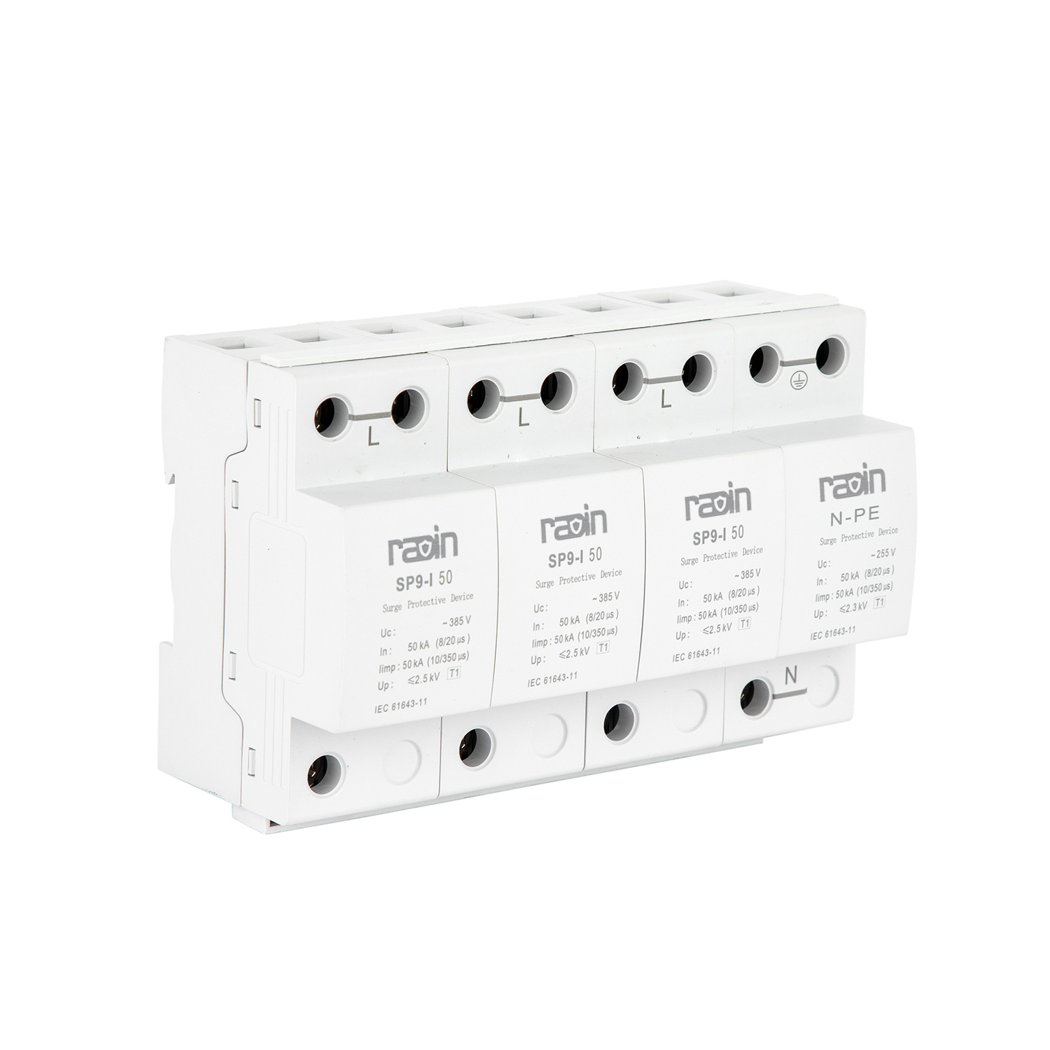
Solar arrays present unique vulnerabilities to transient overvoltages. They feature expansive surface areas mounted on rooftops or open fields. This physical layout creates a massive target for lightning strikes. Furthermore, solar installations rely on complex inverter electronics. These inverters convert DC power to AC power and are highly susceptible to transient damage. A single lightning strike nearby can induce massive voltage spikes across the long DC cable runs, instantly destroying the inverter's sensitive internal components. Protecting this infrastructure requires specialized engineering and dedicated hardware.
Standard AC protectors cannot operate safely in DC applications. AC current naturally crosses zero volts 120 times per second in a 60Hz system. This zero-crossing naturally extinguishes electrical arcs when internal components disconnect. DC current provides no zero-crossing. It flows continuously at full voltage. Modern commercial solar farms operate at 1000V or 1500V DC to maximize efficiency. At these voltages, a sustained arc fault will melt through steel enclosures. If a standard MOV fails in a DC system, the continuous current will sustain an electrical arc across the failed component. This creates a severe fire hazard. DC-specific devices incorporate specialized thermal disconnects, wider physical gaps, and dedicated arc-extinguishing chambers to break this continuous current safely during a catastrophic failure.
Proper solar protection requires strategic placement across the entire DC architecture. You must install a photovoltaic DC surge protector at multiple points to ensure comprehensive coverage. Place them at the solar panels, inside the combiner box, and directly at the inverter DC input. Long cable runs between these components act as massive antennas, inducing transient voltages during nearby lightning strikes. If the distance between the combiner box and the inverter exceeds 10 meters, you must install protection at both ends of that cable run. Always ensure the selected devices comply with specific IEC 61643-31 and UL 1449 standards governing photovoltaic applications.
Translating technical datasheet specifications into real-world protection outcomes is critical for facility managers and electrical contractors. You must match the hardware capabilities to the specific vulnerabilities of your facility. Misinterpreting these metrics leads to undersized protection, wasted capital, or a false sense of security. We evaluate four primary dimensions when specifying hardware for commercial applications.
MCOV dictates the maximum voltage the device can withstand continuously without degrading or entering its clamping state. You must size the MCOV appropriately above the nominal system voltage. A common engineering rule dictates setting MCOV 15% to 25% higher than the nominal voltage. For example, on a 277/480V system, you would specify an MCOV of at least 320V for the 277V legs. If the MCOV is too low, normal grid fluctuations and minor overvoltages will cause premature MOV degradation. The device will constantly try to clamp normal power. If the MCOV is too high, the device will allow too much transient voltage through before it begins to clamp, leaving downstream equipment vulnerable.
VPR represents the most critical metric for equipment safety. It defines the actual clamped voltage the device allows through to the load during a standardized surge event. Lower VPR numbers indicate superior protection. For example, a device with a 600V VPR protects sensitive 120V electronics much better than a device with a 1200V VPR. Always prioritize low let-through voltage for critical loads. When reviewing datasheets, ensure the VPR is tested at the actual installation lead length, as laboratory numbers often assume zero lead length, which is impossible in the field.
Many professionals misunderstand surge current capacity. Higher kA ratings do not necessarily mean a lower let-through voltage. Instead, higher kA ratings equate to a longer operational lifespan and higher fault tolerance. A 200kA device will survive many more moderate surges than a 50kA device before requiring replacement. The larger physical size and parallel MOV arrays in high kA units dissipate heat more effectively. We specify higher ratings for main service entrances and facilities located in high-lightning regions to reduce maintenance frequency and ensure the device survives catastrophic events.
Modern devices sacrifice themselves to protect your equipment. Therefore, you must know exactly when they have failed. Evaluate the necessity of onboard diagnostics during the specification phase. Visual indicators, such as green and red mechanical flags, provide quick status checks for maintenance personnel walking the floor. Audible alarms alert nearby personnel to immediate failures. Remote dry contacts integrate directly with Building Management Systems (BMS) or SCADA networks. This integration allows maintenance teams to monitor device health remotely and dispatch replacements proactively before the next storm hits.
Specification Metric | Technical Definition | Field Application Impact |
|---|---|---|
MCOV | Maximum Continuous Operating Voltage | Determines the threshold before clamping begins. Must exceed nominal grid voltage by 15-25% to prevent premature thermal failure from normal grid fluctuations. |
VPR | Voltage Protection Rating | The actual voltage allowed through to the load during a surge. Lower values provide better protection for sensitive microprocessors and PLCs. |
kA Rating | Surge Current Capacity per Phase | Maximum current the device can divert. Higher values indicate longer operational lifespan, better heat dissipation, and durability against multiple strikes. |
Dry Contacts | Remote Monitoring Relays | Allows integration with facility BMS. Alerts maintenance personnel immediately when the unit sacrifices itself and requires a module replacement. |
Enclosure Rating | NEMA or IP Classification | Dictates where the unit can be installed. NEMA 4X is required for outdoor, harsh, or corrosive environments like solar arrays or water treatment plants. |
A surge protector is only as effective as its grounding system. The device does not make the surge disappear; it diverts it. Without a low-impedance path to ground, the excess electrical energy seeks alternative paths. It will travel through your connected equipment, causing severe damage to power supplies and communication boards. Facility grounding resistance must remain low. Sensitive electronic environments typically require ground resistance below 5 ohms. Conduct regular fall-of-potential testing to ensure grounding integrity remains intact year-round. Soil conditions change with weather and moisture levels, directly impacting ground resistance.
Installation physics directly impact device performance in the field. Every inch of wire adds impedance to the circuit. During a high-frequency transient event, this impedance creates a significant voltage drop. Excess lead length increases the actual let-through voltage reaching your equipment, negating the benefits of a premium device. A common engineering rule states that every inch of lead wire adds roughly 10 to 15 volts to the VPR. Keep installation leads as short and straight as possible. Avoid sharp bends, right angles, or loops in the wiring, as these create inductive choke points that restrict the flow of surge current to ground. To combat this, engineers often utilize a Kelvin connection, also known as V-wiring or in-line wiring. This technique routes the main power conductors directly through the SPD terminals, effectively eliminating lead length impedance.
MOVs degrade silently over time as they diffuse multiple surges. They do not last forever. Facilities must implement a proactive maintenance schedule to prevent unprotected exposure. Conduct visual inspections immediately following major storm seasons, known grid events, or utility switching anomalies. Utilize thermal imaging cameras during routine panel inspections. Thermal imaging can detect failing MOVs generating excess heat before they fail completely and trigger the mechanical flags. Replace modular cartridges immediately when indicators show diminished capacity. Keep spare modules on-site to minimize downtime.
Audit your facility grounding system using a fall-of-potential test to verify resistance remains below 5 ohms.
Map a cascaded protection architecture starting from the main service entrance down to critical point-of-use sub-panels.
Specify MCOV values at least 15% above your nominal system voltage to prevent premature component degradation.
Install dedicated DC-rated protection hardware at all solar combiner boxes and inverter inputs to prevent sustained arc faults.
Integrate all remote monitoring dry contacts into your Building Management System for real-time failure alerts.
A: Surge arresters typically refer to high-voltage utility applications or T1 class devices installed at the main service entrance. They handle massive external transients like direct lightning strikes. Surge protectors cover a broader spectrum, including low-voltage distribution and point-of-use applications to manage smaller, internally generated transients from machinery.
A: Most commercial devices feature visual status indicator lights or mechanical flags on the front face. Green indicates normal operation, while red indicates failure. Advanced units also include remote monitoring dry contacts that send automated failure alerts directly to a facility Building Management System.
A: No. A grounding path is absolutely necessary for transient diversion. The device functions by shunting excess current to ground. Without this low-impedance path, the surge seeks alternative routes through your connected equipment, causing severe damage to power supplies and logic boards.
A: You install a T1 class device at the main electrical service entrance. Its specific application is to handle high-energy external transients, such as direct or partial lightning strikes. It diffuses massive thermal energy before it enters the facility distribution network, acting as the primary defense line.
A: Solar panels generate continuous DC voltage, which lacks the natural zero-crossing of AC power. Standard AC devices cannot extinguish DC arcs. Photovoltaic-specific protectors contain specialized internal components, wider gaps, and thermal disconnects to safely extinguish continuous DC arcs during a surge event.
A: Lifespan is not dictated by a strict chronological timeline. It depends entirely on the frequency and magnitude of the surges it processes. A device in a high-lightning area degrades faster. Higher kA ratings provide greater durability, better heat dissipation, and a longer operational lifespan under heavy surge conditions.
A: Yes, advanced models incorporate EMI/RFI filtering networks. This filtering eliminates high-frequency electromagnetic interference and radio frequency interference riding on the power wave. Scrubbing this electrical line noise protects sensitive microprocessors from logic errors, data corruption, and long-term hardware degradation.